

A flaw’s depth and the material being inspected determine when to use magnetic particle testing . The method is suited to ferromagnetic materials, including iron, nickel, cobalt and some of their alloys, when the aim is to detect surface or shallow subsurface discontinuities. It is not designed to find deeper flaws.
That distinction matters when choosing an NDT method. Magnetic particle testing works by magnetising the component, so it cannot be used on every material. It can reveal discontinuities in castings, forgings and weldments, with results affected by the magnetisation method and particles selected.
This article explains how magnetic particle testing works, which materials and discontinuities it can examine, and when its detection limits make another method more suitable. It also compares dry and wet particles, including visible and fluorescent options, and explains how the inspection approach affects the indications revealed.
Key Takeaways
- Assess the material and the likely flaw depth before selecting magnetic particle inspection; these determine whether the method fits the examination.
- Compare dry, wet, visible and fluorescent particles to choose an approach suited to surface condition and indication visibility.
- Consider magnetisation direction and current type, since they influence which discontinuities can be revealed.
- Recognise where the method applies across industrial sectors, and where its detection limits make another NDT technique more appropriate.
- Use the article’s comparison of magnetic particle testing with other inspection options to identify a suitable examination path.
What Is Magnetic Particle Testing and How Is It Used in NDT?
Magnetic particle testing uses magnetisation and particles to reveal discontinuities in suitable components. The decision about when to use magnetic particle testing depends on the material, flaw location and inspection objective.
MT Advantages and Limitations
The method can reveal surface and shallow subsurface discontinuities in castings, forgings and weldments. It is relatively quick to apply and usually requires less critical surface preparation than some other NDT methods. This can make it useful for examining accessible areas during fabrication or maintenance.
Its limits are equally important. The component must be magnetisable, and the method is not intended to detect deeper flaws. Indications also depend on applying a suitable magnetic field relative to the discontinuity. ISO 17638 covers magnetic particle testing of welds, while ISO 9934-1 sets out general principles.
There is no single inspection interval for every weld or item of equipment. The schedule depends on the applicable code, service conditions and inspection plan. Maintenance programmes may set examination points based on asset condition and the purpose of the inspection.
Choosing MT Over Other Testing Methods
Use magnetic particle testing when a ferromagnetic component needs to be examined for surface or near-surface discontinuities. Unlike Dye Penetrant Inspection, it can also reveal shallow subsurface indications. It does not replace Ultrasonic Inspection when deeper internal flaws need to be assessed.
To decide when to use magnetic particle testing, consider the material and expected flaw depth. If the material cannot be magnetised or the flaw lies deeper within the component, this method cannot answer the inspection question. Select the technique to match the examination objective.
Governing MT Standards
For British and European work, ISO 9934-1 provides general principles for magnetic particle testing, while ISO 17638 addresses weld testing. The project specification establishes the relevant inspection procedure and acceptance criteria.
For work governed by US requirements, ASTM E1444 and applicable ASME requirements may be relevant. The governing project code and specification determine which requirements apply. US references should not be treated as interchangeable with ISO standards; the inspection procedure must follow the requirements set for the component.
A typical inspection involves preparing the examination area, magnetising the component, applying particles and examining any indications. The inspector evaluates and records relevant indications against the applicable procedure and acceptance criteria. The sequence depends on the selected technique and governing requirements.
Inspection controls should address the equipment, particles and viewing conditions. Follow the approved procedure for equipment use and particle handling, and apply site controls for electrical equipment and fluorescent examination under ultraviolet light. Keep the examination area accessible for safe application and clear evaluation.
Dry, wet, visible, and fluorescent particles
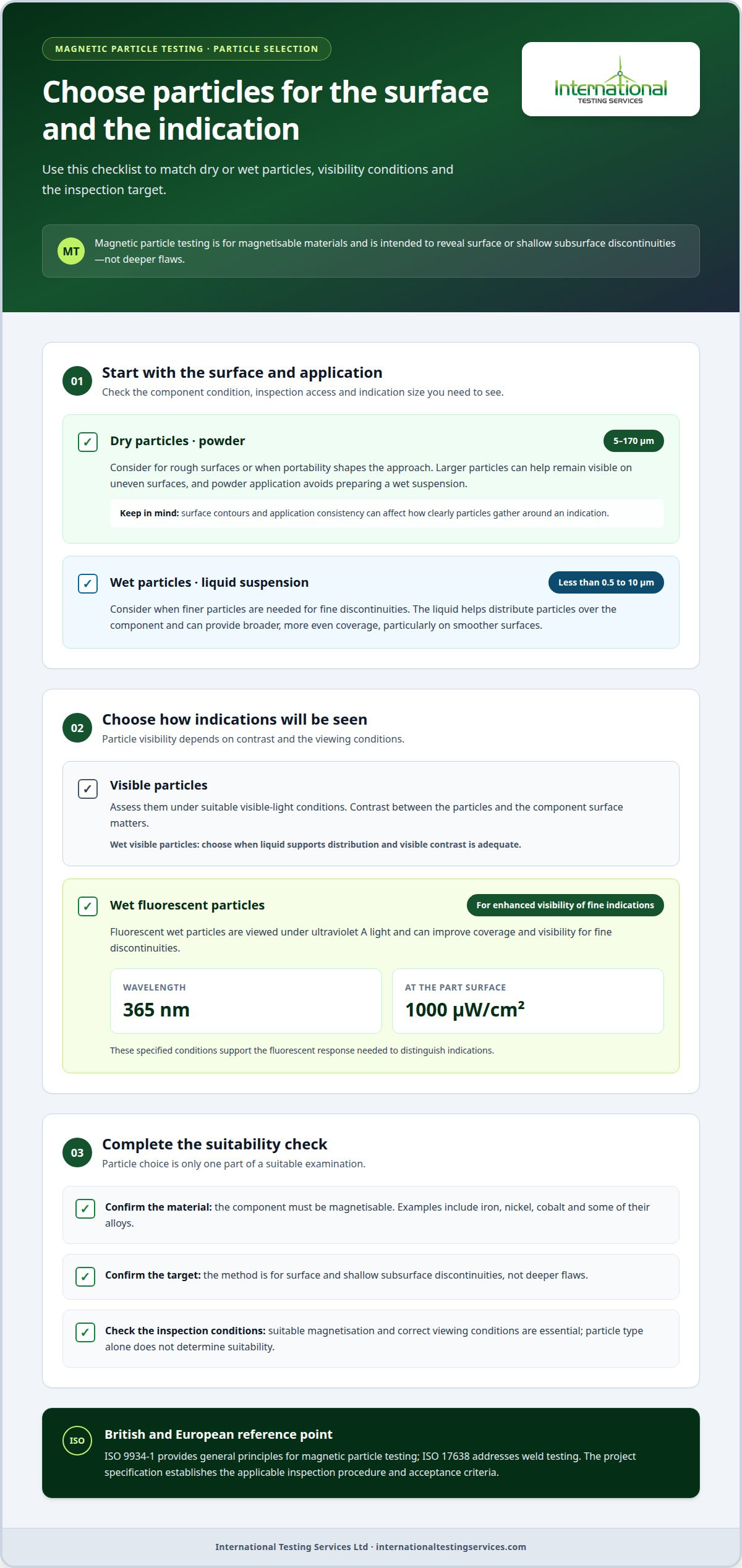
Particle selection affects how discontinuities appear during Magnetic Particle Inspection. The main options are dry powder or wet suspension, each available in visible or fluorescent forms. Choose the approach according to the component’s surface condition, inspection access and the size of indications that need to be seen.
Dry particles are applied as powder and suit rough surfaces or inspections requiring portability. Their particle sizes range from 5 to 170 micrometers. The larger size range can help particles remain visible on uneven surfaces, while powder application avoids preparing a wet suspension. However, surface contours and application consistency can affect how clearly particles gather around an indication.
Wet systems suspend particles in a liquid carrier and apply them across the examination area. Their particles range from less than 0.5 to 10 micrometers. The finer particles support detection of fine discontinuities, while the liquid helps distribute them over the component surface. Wet application can provide broader, more even coverage than dry powder, particularly on smoother surfaces.
Visible particles are assessed under suitable visible-light conditions, so contrast between the particles and component surface matters. Fluorescent wet particles are viewed under ultraviolet A light and provide improved coverage and visibility for fine discontinuities. The light must have a wavelength of 365 nm, with 1000 μW/cm2 at the part surface for proper inspection. These conditions support the fluorescent response needed to distinguish indications.
- Use dry visible powder where roughness or portability shapes the inspection approach.
- Use wet visible particles where liquid suspension supports particle distribution and visible contrast is adequate.
- Use wet fluorescent particles where fine indications require enhanced visibility and the specified ultraviolet conditions are available.
Particle type alone does not determine whether the inspection is suitable. The examiner also considers the component’s surface, the discontinuity being sought and the inspection conditions. For example, fluorescent particles may help reveal a fine indication, but effective magnetisation and correct viewing conditions are still essential. An unsuitable particle choice can make relevant indications harder to distinguish.
For particle-based examinations, Magnetic Particle Inspection provides the method suited to magnetisable components and surface or shallow subsurface discontinuities. Matching the particle form to the inspection conditions helps maintain clear, interpretable indications.
Ferromagnetic material requirements
Magnetic particle testing requires a component that can be magnetised. Check material suitability before choosing particles or setting inspection conditions.
Ferromagnetic Material Eligibility
Ferromagnetic materials respond strongly enough to an applied magnetic field for magnetic particle testing. Suitable examples include iron, nickel, cobalt and some of their alloys. The method relies on magnetising the component so particles can gather at leakage fields caused by discontinuities. A material that cannot be magnetised does not meet this basic requirement.
This distinction matters for mixed-material assemblies and components of uncertain composition. A steel part may be suitable, while an attached or adjoining material may not be. The inspection scope should identify the specific component or area being assessed, rather than treating an entire assembly as one material.
Material identification also matters when alloy composition affects magnetic response. A broad material-family name may not be enough to establish suitability: the actual material must be capable of magnetisation. The inspection plan should therefore identify the component material and examination area first.
Surface Preparation and Part Conditions
Surface preparation means making the examination area suitable for magnetisation, particle application and indication assessment. Magnetic particle testing can require less critical surface preparation than some other NDT methods, but surface condition still affects results. For example, a rough surface can influence particle movement and make indications harder to distinguish.
Assess the component’s condition before applying particles. The examination area must be accessible to the magnetising equipment and visible for evaluation. Dry powder can be suitable for rough surfaces, and portability may influence the method choice. Wet suspension distributes particles across the surface, so surface condition still matters for coverage and interpretation.
Consider surface features alongside material suitability. Weld profiles, casting contours and forging surfaces can create uneven examination areas. These shapes do not automatically rule out testing, but they can affect particle accumulation and indication clarity. The chosen method and viewing conditions should account for the actual surface.
Part condition also includes whether the target area can be magnetised in the required direction. A discontinuity’s orientation relative to the magnetic field affects whether leakage develops where particles can gather. An accessible surface may still be unsuitable for effective examination if it cannot be magnetised appropriately. Material, surface condition and access all affect suitability.
Before inspection, define the target material and area, then assess surface condition and access. This helps distinguish a material limitation from a preparation or access issue, and supports a clear decision about whether magnetic particle testing suits the component.
MT inspection in energy, aerospace, transportation, manufacturing, and infrastructure
Magnetic particle testing is used across industries where examination needs and component materials make the method suitable. Sector alone does not determine suitability; the component and inspection target matter.
MT Inspection in Energy and Aerospace
In energy, Magnetic Particle Inspection is used in petrochemical and power generation settings. It can help examine suitable components for surface and shallow subsurface discontinuities during fabrication or maintenance. The inspection question should guide method selection: the material must be magnetisable, and the target flaw must fall within the method’s detection scope.
Aerospace also uses Magnetic Particle Inspection, with requirements varying by component and material. The method can support focused assessment of ferromagnetic parts, but it does not replace methods intended to detect deeper internal flaws. This distinction helps engineers align the inspection approach with the damage mechanism and required coverage.
MT Inspection in Transportation, Manufacturing, and Infrastructure
Transportation applications include automotive work, while manufacturing covers components made through processes such as casting, forging and welding. Magnetic Particle Inspection can examine suitable ferromagnetic components in these settings. The inspection plan should identify the relevant area and discontinuity, rather than assume the industry or production process means the method is suitable.
Structural steel is another application, linking the method to infrastructure inspection. Magnetic Particle Inspection may also be used underwater on offshore structures and underwater pipelines. In these situations, the inspection environment adds access and visibility considerations to the assessment of material and flaws.
In power generation and petrochemical facilities, an asset’s service context helps define the inspection objective. An examination may focus on a known area of concern or form part of planned maintenance. In either case, magnetic particle testing is appropriate only when the target material and discontinuity match its capabilities.
For aerospace and automotive components, geometry and access can affect examination coverage. Complex shapes may restrict where magnetising equipment can be positioned or where indications can be viewed. The inspection procedure should define the examination area and ensure the required surfaces can be assessed effectively.
Manufacturing teams can use the method to examine ferromagnetic castings, forgings or weldments as part of quality control. The production stage matters because the inspection target may differ between fabrication and later service. A weld examination, for example, focuses on the weld area and follows the applicable procedure.
Infrastructure work can involve large structural steel areas, offshore structures or underwater pipelines. Inspection planning must account for the target area and its accessibility, as well as whether the material can be magnetised. The sector suggests possible applications, but assessment of the specific component determines whether magnetic particle testing is appropriate.
Surface and near-surface discontinuity detection
Magnetic particle testing is primarily effective for surface and near-surface discontinuities in magnetisable components. It reveals indications through magnetic flux leakage, so flaw depth and orientation relative to the magnetic field matter.
Alternating current (AC) is commonly selected for surface discontinuities. It creates a strong surface field but does not penetrate deeply, making it suitable for surface cracks. This current choice is relevant when the examination targets flaws open to or close to the component surface.
Direct current (DC) can provide greater penetration for shallow subsurface discontinuities. Full-wave DC is used when AC does not penetrate far enough to magnetise the part at the required depth. Half-wave DC can detect surface-breaking indications and penetrates farther into a part than full-wave DC. These options suit different examination needs, rather than making one current type universally preferable.
Field direction also affects whether an indication forms. Circular magnetisation is suited to detecting longitudinal discontinuities, while longitudinal magnetisation is effective for transverse discontinuities. A field aligned with a discontinuity may produce less useful leakage than one crossing it. The inspector considers the likely flaw direction when selecting the magnetisation method.
A magnetic yoke requires rotation by 90 degrees for each inspection area to detect horizontal and vertical discontinuities. This change in orientation provides coverage in both directions across the examined area. A single field direction may leave differently oriented discontinuities less detectable, so the inspection sequence must account for the required coverage.
These distinctions help define the method’s limits. Magnetic particle testing is not intended to find deep flaws, and indications depend on suitable magnetisation and particle response. If the inspection target lies beyond the near-surface zone, another NDT method may be more appropriate for assessing internal discontinuities.
For a weld, ISO 17638 covers magnetic particle testing, and the procedure should align the field direction with the discontinuities being assessed. An example is using suitable magnetisation to assess a weld area for transverse or longitudinal indications. Current type, component geometry and expected flaw orientation together shape the inspection approach.
To assess a ferromagnetic component for surface or shallow subsurface indications, arrange a magnetic particle inspection suited to the examination target.
Alternating current is commonly used in Magnetic Particle Inspection to detect surface discontinuities. The selected current helps define the inspection objective: the method targets indications at or close to the surface, rather than searching for every possible flaw. Consider the anticipated discontinuity location alongside field direction and the area being examined. A useful indication depends not only on applying magnetisation, but also on choosing conditions that make leakage from the relevant flaw visible.
When the inspection focuses on surface discontinuities, keep the target clear while planning coverage. If an indication may lie beneath the surface, reconsider the current and technique in light of the component and required depth, rather than assuming a surface-oriented approach will answer the question. This keeps conclusions proportionate: no visible indication under one setup does not establish that a deeper discontinuity is absent.
International Testing Services: Phased Array Inspection
International Testing Services Ltd provides Phased Array Inspection for examination requirements beyond the scope of magnetic particle testing. When an assessment needs to examine deeper internal discontinuities, Phased Array Inspection, TOFD Inspection or Ultrasonic Inspection may be suitable. The method should match the component, inspection objective and applicable requirements.
For components where the target is a surface or shallow subsurface discontinuity, Magnetic Particle Inspection remains relevant. If the required examination extends beyond that scope, International Testing Services Ltd can help identify an appropriate approach through its inspection services.
Contact International Testing Services Ltd to discuss your NDT inspection requirements.
Set the Next Inspection Decision
A sound inspection decision translates the examination objective into a clear technical scope. Before scheduling work, align the required coverage, applicable acceptance criteria and intended use of the findings. This gives the inspection a defined role in project quality and maintenance decisions.
Deciding when to use magnetic particle testing starts with matching the method to the question the inspection must answer. If the assessment calls for another approach, International Testing Services Ltd offers Phased Array Inspection, TOFD Inspection and Ultrasonic Inspection. The appropriate method depends on the examination objective and component requirements.
Bring the inspection scope and relevant project requirements into the discussion so the next step can be considered in context. Contact International Testing Services Ltd to discuss your NDT inspection needs and identify a suitable way forward.
A well-defined examination supports informed decisions about component integrity and project priorities.
Frequently Asked Questions
What is magnetic particle testing used for?
Magnetic particle testing locates discontinuities in components that can be magnetised. For example, an inspection may examine a weld area or forged component for indications that could affect integrity. It can be used during manufacturing or maintenance, depending on the objective. The findings help determine whether an indication needs assessment against the project’s acceptance criteria.
Which materials can be inspected with magnetic particle testing?
Magnetic particle testing can examine ferromagnetic materials, including iron, nickel, cobalt and some of their alloys. A material name alone may not establish suitability for a particular component, especially in an assembly containing different materials. For example, a steel section can be assessed, while an attached non-magnetisable section cannot be examined by this method. Identify the target material and inspection area before selecting the technique.
What types of cracks and defects can magnetic particle testing detect?
It can reveal surface-breaking and shallow subsurface discontinuities, including cracks, when their orientation and magnetisation produce detectable leakage. For example, a crack across a weld may respond differently from one running along it, so inspection coverage must account for possible directions. Magnetic particle indications show where particles gather; their relevance is assessed against the applicable examination procedure and acceptance criteria.
What are the limitations of magnetic particle testing?
The method is limited to magnetisable materials and is primarily effective for surface and near-surface discontinuities. It is not suitable for assessing deeper internal flaws, such as a defect far below the component surface. Complex geometry or restricted access can also make it harder to apply the required magnetic field or examine an area adequately. Ultrasonic Inspection may be more appropriate when deeper coverage is required.
What safety risks and precautions apply to magnetic particle inspection?
Follow the approved procedure for equipment use and particle handling, and apply site controls for electrical equipment and fluorescent examination under ultraviolet light. Keep the examination area accessible for safe application and clear evaluation.


