

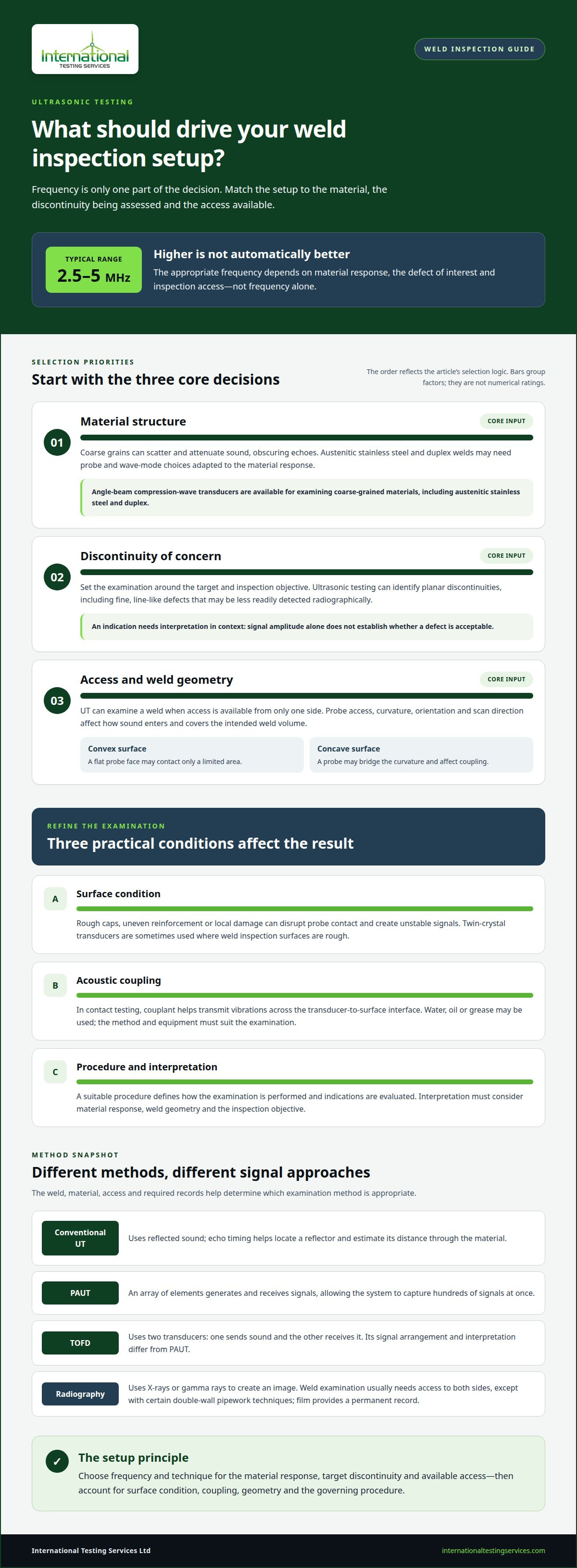
The highest frequency is not automatically the best choice for a weld. Ultrasonic weld inspection generally uses frequencies from 2.5 to 5 MHz, but the appropriate setting depends on the material, the defect being assessed and the inspection access. The method sends sound into the component and evaluates reflected signals to locate and assess discontinuities.
It’s understandable to focus on frequency when selecting an ultrasonic weld inspection method: frequency affects how sound travels through a material and how clearly indications can be resolved. But it is only one part of the decision. Material structure, surface condition, couplant, weld geometry and access all affect whether the examination can produce useful results.
This article explains how ultrasonic testing examines welds, what its limitations mean in practice, and how frequency relates to material and inspection conditions. It also compares conventional ultrasonic testing with phased array and time-of-flight diffraction, helping you understand how method selection supports a reliable assessment.
Key Takeaways
- Match probe selection to the material structure and surface condition; coarse-grained welds can scatter sound and complicate interpretation.
- Choose between ultrasonic and radiographic methods by considering the discontinuities of concern and access to the joint.
- Use a suitable couplant to improve sound transmission across the transducer-to-surface interface.
- Balance frequency against the inspection objective and material response rather than treating a higher setting as automatically better.
- Apply the governing procedure and relevant standard to define the examination scope and assess indications consistently.
Ultrasonic testing advantages and limitations
The main weld examination methods include conventional ultrasonic testing, phased array ultrasonic testing (PAUT) and time-of-flight diffraction (TOFD). They use reflected or diffracted sound to assess internal discontinuities, while radiographic testing uses radiation to create an image of the weld.
Method selection depends on the weld, material, inspection access and required records. Each technique has distinct strengths and limitations when examining infrastructure and mechanical components.
Contact, Immersion, and Air-Coupled Methods
Contact testing places a transducer against the component, with couplant between the probe and surface. Immersion testing uses water as the acoustic path, while air-coupled testing sends sound across an air gap. The distinction matters because effective energy transfer depends on the interface between the transducer and test piece.
In contact examinations, couplant such as water, oil or grease helps transmit vibrations into the material. Immersion can maintain a consistent water path, while air-coupled testing avoids liquid contact. The method must suit the examination and equipment, so surface condition and access also influence practical selection.
Phased Array and TOFD Methods
PAUT uses an array of elements to generate and receive ultrasonic signals, allowing the system to capture hundreds of signals at once. TOFD uses two transducers: one sends sound and the other receives it. Both methods support weld assessment, but their signal arrangements and interpretation differ.
For phased-array contact testing, ASTM International identifies ASTM E2700-26 as the 2026 edition of Standard Practice for Contact Ultrasonic Testing of Welds Using Phased Arrays. A suitable procedure defines how the examination is performed and indications are evaluated. The operator must interpret results in relation to weld geometry and the inspection objective.
Ultrasonic testing directs high-frequency mechanical vibrations into a component and evaluates energy reflected by discontinuities. Echo timing helps locate a reflector, while sound travel through a given material helps estimate its distance. The method can examine ferrous and nonferrous materials, including where access is available from only one side.
These capabilities support internal assessment without damaging the weld. Ultrasonic testing can identify planar discontinuities, including fine, line-like defects, that may be less readily detected radiographically. Limitations include dependence on operator competence, a suitable procedure, material response and probe access. An indication requires interpretation: signal amplitude alone does not establish whether a defect is acceptable.
Radiographic testing sends X-rays or gamma rays through a weld to create an image on film. After development, areas exposed to more radiation appear darker, while areas receiving less exposure remain lighter. For example, low-density slag inclusions appear dark, while high-density tungsten inclusions appear light.
Radiography can reveal porosity, inclusions, cracks and voids, and film provides a permanent record for qualified interpretation. Weld examination usually requires access to both sides, except with certain double-wall imaging techniques on pipework. Radiation also requires suitably trained and qualified personnel. Defect type and access, alongside these requirements, help guide the choice between radiographic and ultrasonic testing.
Coarse-grained materials and rough surfaces
Coarse-grained weld metals change how sound travels through a component. Grain boundaries scatter and attenuate energy, potentially obscuring echoes from internal discontinuities. Austenitic stainless steel and duplex materials are examples where grain structure can complicate ultrasonic examination. Probe selection and signal interpretation must account for the material rather than treating every weld as carbon steel.
Angle-beam compression-wave transducers are available for examining coarse-grained materials, including austenitic stainless steel and duplex. Their use reflects the need to adapt the wave mode and inspection arrangement to the material response. The operator assesses whether the signals provide meaningful coverage and interpretable indications. Fabrication records, weld configuration and examination objectives help establish the context.
Surface condition also affects probe contact. A rough weld cap, uneven reinforcement or local damage can disrupt acoustic coupling and produce unstable signals. Twin-crystal transducers are sometimes used for weld inspection where contact surfaces are rough. Their configuration can help address near-surface conditions, but the examination still relies on suitable probe placement and a controlled scanning pattern.
Convex and concave surfaces create different contact challenges. On a convex surface, a flat probe face may touch only a limited area; on a concave surface, the probe may bridge the curvature. Either can affect coupling and beam entry. The inspection approach accounts for curvature, probe orientation and scan direction to direct the sound path through the intended weld volume.
Visual Inspection addresses visible surface conditions that matter when interpreting internal testing. Undercut, surface-breaking cracks, weld profile irregularities and spatter can affect the examination surface or signal response. Visual examination also records the accessible condition and weld profile. It cannot establish that subsurface discontinuities are absent, so it complements rather than replaces an appropriate volumetric method.
Surface and subsurface discontinuities need different detection approaches. A surface-breaking crack may be visible or assessed using a surface-sensitive method, while internal lack of fusion or an inclusion requires examination through the material. Sound reflection and scattering can make near-surface indications difficult to distinguish from probe-related signals, particularly on rough welds. Interpretation considers indication position, shape, repeatability and weld geometry.
For a fabricated component with a rough cap and coarse-grained stainless weld, the sequence matters: assess the surface, select a compatible probe arrangement, then scan using a defined coverage pattern. Operator training supports consistent recognition of material noise and relevant indications. Together, these controls strengthen weld integrity assessment without treating a difficult surface or noisy signal as proof of a defect.
Comparing inspection methods by defect type and joint access
Choose an examination method based on the discontinuities of concern, weld geometry and inspection objective. The useful comparison is not simply which technique detects more, but whether its evidence answers the project’s specific question.
Defect Types and Positioning
Discontinuity type and orientation affect how each method responds. Ultrasonic signals depend on the sound beam meeting a reflector, while radiographic indications depend on changes in radiation passing through the weld. A planar flaw may therefore produce different evidence from rounded porosity, even in the same joint.
Knowledge of the welding process adds context. For example, slag inclusions would not be expected in a weld deposited using the gas metal arc process. This helps the operator interpret an indication alongside fabrication history rather than relying on signal appearance alone. Position relative to the weld root, face and bevel can also guide further examination.
Inspection planning should match the expected discontinuity to the technique’s detection mechanism. If lack of fusion is the concern, the procedure can orient ultrasonic scans to examine likely fusion boundaries. If the assessment concerns volumetric inclusions or porosity, radiographic image evidence may be relevant. Acceptance criteria then determine how recorded indications are evaluated.
Fine Defect Detection
Fine planar discontinuities can be difficult to distinguish from other responses unless the examination is designed around their likely orientation. Ultrasonic testing can often detect fine, line-like defects that radiography may not reveal as readily. Results depend on sound-beam direction, weld profile and a controlled scan pattern.
Radiographic testing can show internal features through image contrast, but a flaw’s orientation relative to the radiation path affects its visibility. Method selection should therefore start with the defect in question, not an assumption that either technique is universally more sensitive.
For a weld with suspected planar indications, the examination plan should define scan directions that interrogate the relevant planes. Where rounded porosity is the concern, the evidence sought differs, and radiographic imaging may provide a useful record. These examples show how to match technique to the inspection objective, not rules that apply automatically to every component.
Ultrasonic and radiographic results can provide complementary evidence when the project scope calls for more than one method. Each record should include location, relevant indication characteristics and evaluation against the applicable acceptance criteria. This supports traceability when findings are reviewed alongside weld drawings, fabrication records or repair documentation.
Method selection ultimately connects defect shape, likely position, weld process and evaluation requirements. A sound comparison defines what each examination is expected to establish and how findings will be assessed. This produces a more targeted inspection plan than choosing a technique solely by convention.
Couplants and acoustic mismatch
A couplant bridges the interface between an ultrasonic transducer and the test surface. Without it, microscopic air gaps interrupt energy transfer because air and solid materials transmit sound differently. This can weaken echoes from weld discontinuities. When examining a fabricated steel joint, couplant selection and consistent probe contact are part of the setup.
Ultrasonic testing equipment sends an electrical pulse to the transducer, which converts it into mechanical vibration. The vibration must pass through the couplant and into the component before returning echoes can be assessed. Water, oil and grease are common choices. Each provides a transmission path, but the medium must suit the surface, probe arrangement and examination procedure.
A thin, continuous film is generally more useful than intermittent contact. As a probe moves across a rough weld cap, gaps beneath its face can cause unstable signals. The operator maintains contact and monitors signal behaviour while scanning. On a curved component, the probe face and contact area also affect how consistently energy enters the material.
Transducer design and couplant work together. A contact probe relies on couplant at the component surface, while an immersion arrangement uses water between the transducer and test piece. In both configurations, the intervening medium forms part of the sound path. Air-coupled techniques avoid liquid couplant, but the air path presents a distinct transmission challenge and requires equipment designed for that application.
Acoustic mismatch describes the difference in how adjoining materials respond to sound. At a transducer-to-steel boundary, couplant reduces the air gap that would otherwise reflect much of the incident energy. It does not eliminate every reflection. Equipment also records echoes from weld geometry, component boundaries and relevant discontinuities, which the operator distinguishes during interpretation.
Manufacturing conditions can change the surface presented for examination. Weld spatter, scale, coatings or uneven reinforcement may disrupt probe contact or obstruct the intended scan path. Before scanning, the setup accounts for surface condition and the procedure’s requirements. Where preparation is necessary, it supports stable contact without changing the weld’s acceptance criteria.
Couplant also affects repeatability during a scan. A dry patch can reduce signal strength, while excess or uneven medium can make probe movement difficult. The operator maintains consistent contact and monitors equipment response across the inspection area. These controls help distinguish changes caused by the interface from echoes associated with the weld.
A suitable couplant supports reliable energy transfer and a more consistent signal response. Water, oil or grease is not interchangeable in every setup: component orientation, surface condition, transducer type and procedure all influence the choice. Matching the medium and equipment to the examination helps produce interpretable results across the weld rather than isolated, inconsistent readings.
Ultrasonic frequency ranges for weld inspection
Frequency affects how an ultrasonic signal interacts with weld metal. Weld examination generally uses 2.5 to 5 MHz, with selection influenced by material structure, section thickness and the discontinuities sought.
Higher frequency can improve response to fine reflectors, but sound may attenuate more rapidly in coarse-grained material. Lower frequency can travel farther through the component, but may provide less detail for small indications. The operator balances penetration and resolution against the material’s response rather than choosing frequency in isolation.
For example, a 4 MHz angle-beam probe is one available weld-inspection configuration. Ultrasonic testing uses a range of sound frequencies, depending on the application. These ranges cover different applications; they do not prescribe one setting for every weld or industry.
Unlike destructive testing, ultrasonic examination evaluates a component without cutting it apart. An electrical pulse excites the transducer, which generates sound waves in the material. Reflected signals return to the equipment for interpretation. The method uses mechanical sound, not the ionising radiation used in radiographic testing.
For UK and European projects, relevant ultrasonic-testing standards include ISO 16810:2024 and ISO 5577:2017. The applicable construction code, contract specification and inspection plan define the examination requirements for each asset. Frequency selection remains part of the procedure and does not, by itself, establish acceptance criteria.
Ultrasonic weld inspectors typically need Level II or Level III certification and competence appropriate to the method and procedure. The required qualification framework depends on the project’s governing specification. Inspectors also need familiarity with the selected equipment, weld geometry and criteria for evaluating indications.
For construction, pipeline or pressure-vessel welds, the project specification and applicable construction or inspection code set the required examination scope. These documents identify which joints require examination and which methods and acceptance criteria apply. Requirements differ by asset and project, so the inspection plan provides the working basis.
A controlled examination follows a defined sequence: review the procedure and weld geometry, select and verify the probe and equipment, prepare the surface and apply couplant, then scan the specified area. The operator evaluates indications against the procedure’s criteria and records the results. Scan direction and coverage must support the required assessment.
Frequency is a method variable, not an acceptance criterion. For a thick or coarse-grained weld, material response may matter more than the preference for fine resolution. For a thinner weld, the examination objective and expected defect orientation guide the balance. The procedure connects these factors to a repeatable assessment.
International Testing Services Ltd: Ultrasonic Inspection
International Testing Services Ltd provides Ultrasonic Inspection for welds requiring internal assessment. The appropriate approach depends on material, weld geometry, access and inspection objective. Phased Array Inspection and TOFD Inspection offer additional ultrasonic methods, while Welding Inspection can support a broader assessment of weld quality.
For a project involving a complex weld configuration or defined examination requirements, these services help align method selection with the inspection scope. Share the relevant weld details and requirements so the examination can be considered in context.
Contact International Testing Services Ltd to discuss your weld inspection requirements.
Set the inspection scope with confidence
Make the next step a clear inspection brief. Identify the component, weld configuration, material, access conditions and governing acceptance criteria. This gives the examination a defined purpose and supports method selection for the project. The final scope depends on those requirements, not frequency alone.
International Testing Services Ltd offers Ultrasonic Inspection, Phased Array Inspection and TOFD Inspection for weld assessment. These methods suit different examination needs, from conventional ultrasonic assessment to phased-array and diffraction approaches. A focused discussion can align the requested examination with the component and required inspection scope.
For a planned or in-service weld examination, contact International Testing Services Ltd to discuss your requirements. A well-defined brief is a practical starting point for effective ultrasonic weld inspection and sound engineering decisions.
Frequently Asked Questions
What Is Ultrasonic Testing and How is it Used in NDT?
Ultrasonic testing is a non-destructive method that uses sound waves to examine a component’s internal condition. In NDT, an operator introduces sound into the material and assesses returning signals for evidence of discontinuities. For example, during fabrication inspection, the technique can assess a weld without cutting or otherwise damaging the joint. The examination procedure defines coverage and how indications are assessed.
What Is an Ultrasonic Weld Test?
An ultrasonic weld test examines a welded joint using an ultrasonic probe and suitable testing equipment. The operator scans the specified area and evaluates responses against the examination procedure and acceptance criteria. For a fabrication project, the test records relevant indications and their locations for assessment. The report supports quality records, but results must be interpreted within the applicable project requirements.
What is ultrasonic weld inspection and how does it work?
Ultrasonic weld inspection assesses a weld by transmitting sound into the material and interpreting returning signals. The equipment displays echoes from the weld and component boundaries, which the operator relates to scan position and geometry. For example, a signal that appears during a scan can be reviewed across adjacent probe positions to assess its consistency. The procedure guides how the indication is recorded and evaluated.
What types of weld defects can ultrasonic testing detect?
Ultrasonic testing can detect internal discontinuities such as cracks, lack of fusion, inclusions and voids, depending on the examination setup and defect orientation. A planar discontinuity may reflect sound differently from rounded porosity, so probe direction and scan coverage affect the response. The operator evaluates indication position and signal behaviour against applicable criteria, rather than deciding defect acceptability from a signal alone.
What equipment is needed for ultrasonic weld inspection?
Typical equipment includes an ultrasonic instrument, a suitable transducer, couplant and the examination references specified by the procedure. The instrument generates and displays signals, while the transducer introduces sound into the weld and receives returning energy. Couplant supports transmission at the contact surface. Probe type and instrument settings are selected for the material, joint geometry and method, with results assessed using the governing procedure.
What are the limitations and risks of ultrasonic weld testing?
Results depend on probe access, surface condition, material structure, defect orientation and operator competence. Coarse-grained metals can scatter sound, while complex geometry can create echoes that require careful interpretation. Ultrasonic testing does not use ionising radiation, but safe component access and controlled handling of couplant remain relevant site considerations. A defined procedure and suitable training help manage limitations and support consistent reporting.
How does ultrasonic testing compare with radiographic weld inspection?
Ultrasonic testing evaluates returning sound signals, while Radiographic Inspection forms an image using X-rays or gamma rays. The methods can reveal different features, and suitability depends on defect type, weld geometry and available access. For example, ultrasonic testing can be practical when examination access is limited to one side; radiography generally requires access on both sides. Radiographic images also provide a permanent record for qualified interpretation.


