
Weld inspection during installation documents whether joints were prepared, welded and examined in line with project requirements. Records may cover materials, fit-up, welding procedures and parameters, visual findings, non-destructive testing results, and how defects were addressed. Planning also identifies critical welds before access becomes restricted or repairs become more complex.
A completed weld may look sound on the surface without meeting every requirement. Checks before and during welding can catch conditions that are harder to assess later, while post-weld examination can identify surface and internal discontinuities. The joint, its service conditions and project documents determine the inspection method and timing.
This article explains what inspectors record, how welded connections are assessed, and how to plan checks around critical locations and applicable standards. It covers material fit-up and cleanliness, inspection at each welding stage, and how visual inspection and non-destructive testing document weld quality and support compliance.
Key Takeaways
- Visual inspection can identify surface discontinuities and dimensional issues, but it cannot reveal every internal flaw.
- In-process checks compare welding conditions with the applicable procedure, including temperature, cleaning and welding sequence.
- Fit-up and surface cleanliness affect weld quality; inspectors assess joint preparation, alignment and contamination before welding.
- Inspection criteria come from the governing project documents, so planning should align examination methods and records with those requirements.
- Identifying critical weld locations early helps schedule inspection at useful stages and address findings before access becomes difficult.
What information is collected during weld inspection?
Inspection records document visible weld condition, measurements, discontinuities and decisions about acceptance or further examination. Visual Inspection provides an initial assessment, but cannot establish that every part of a weld is defect-free.
Good and Defective Weld Appearance
A weld bead should have a profile and dimensions that match the applicable specification, with no visible cracks or abrupt changes. Bead shape, size and continuity can indicate whether the joint meets its stated requirements. Inspectors use welding gauges to compare features such as weld size, leg length and reinforcement height with specified values.
Visible concerns include undercut, overlap, surface porosity, underfill, excessive reinforcement and burn-through. An undersized fillet weld, for example, may fall short of specified dimensions, while an irregular bead may warrant closer examination. Appearance alone cannot prove that a weld will function as intended, so acceptance depends on the governing criteria and any required testing.
Visual Cues of Potential Defects
Visible features can indicate a discontinuity or a condition that needs further assessment. An inspector can identify these concerns and decide whether another examination method is needed. A groove along the weld toe, for example, may indicate undercut, while pores on the surface can point to porosity.
Inspectors also look for cracking, incomplete or excessive root penetration where visible, and signs of distortion. They record findings with their location and relevant measurements. Visual Inspection identifies surface conditions; internal lack of fusion or poor penetration may remain hidden and require a suitable non-destructive testing method.
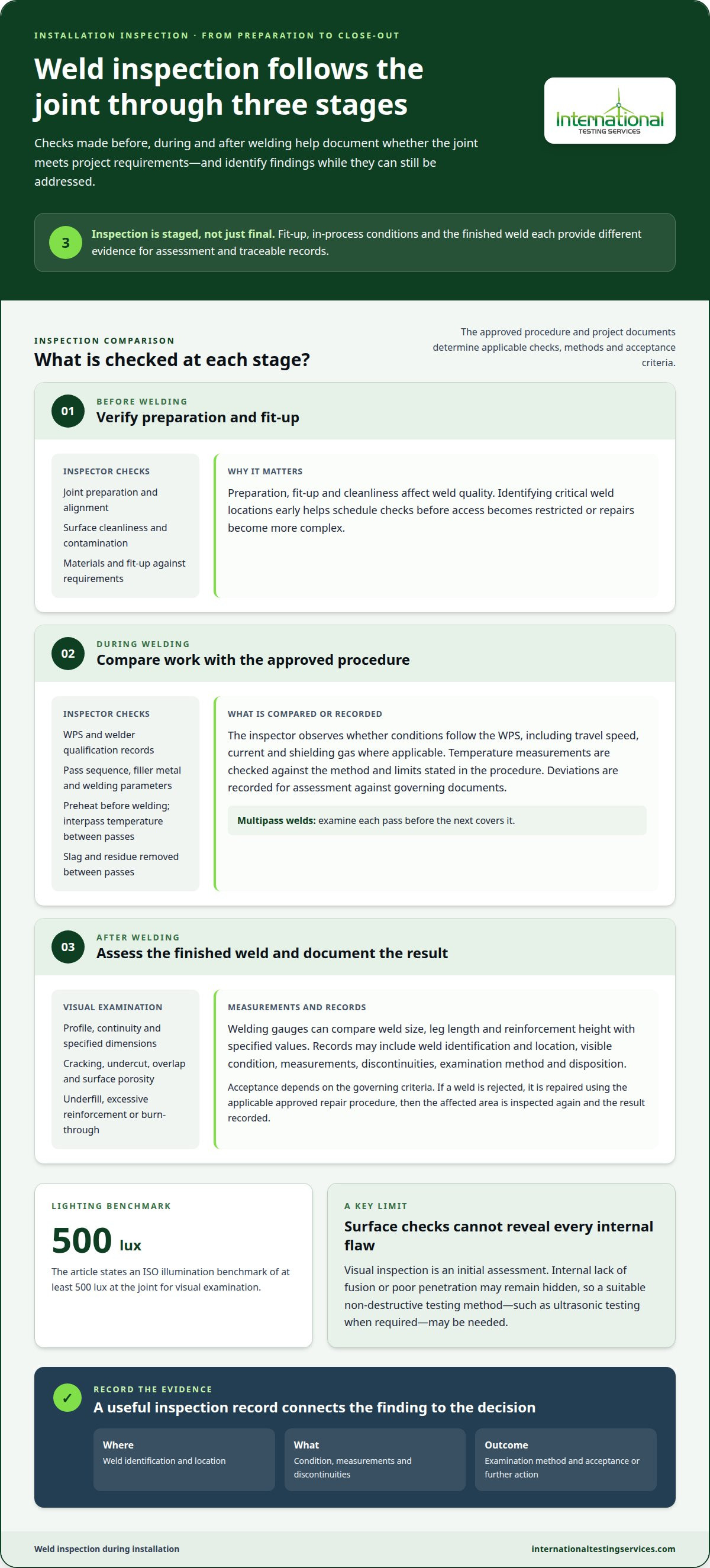
During weld inspection during installation, visual checks can take place before welding, between passes and after completion. Before work begins, the inspector can assess joint preparation and fit-up. For a multipass weld, each pass is examined before the next covers it. After welding, the inspector assesses the finished surface and records findings. Some governing documents require post-weld visual examination of all welds, but the project requirements determine the applicable extent.
Lighting affects what the inspector can see. The stated ISO illumination benchmark for visual examination is at least 500 lux at the joint. Even with adequate lighting, visual inspection cannot reliably reveal every internal discontinuity. It is therefore a useful initial assessment, not a substitute for ultrasonic or other examination when the specification calls for further testing. Surface condition and access also affect whether relevant features can be examined.
Records may include the weld location and identification, visible condition, measurements, discontinuities, examination method and disposition. For example, an inspector can record undercut at a weld toe and note whether it meets the specified acceptance criteria. This documented result supports traceability and helps determine whether the weld is accepted or needs further action.
A rejected weld is repaired using the applicable approved repair procedure, then the affected area is inspected again. Re-examination confirms whether the repair meets the relevant acceptance criteria, and the result is added to the inspection record.
Common site risks include restricted access, unstable working positions, hot surfaces and nearby welding operations. Inspection planning should address safe access, suitable lighting, coordination with site controls and protection from active work. Radiographic testing also requires controls for radiation hazards.
How To Inspect Welded Connections?
Inspection follows the approved welding procedure from preparation through final examination. The inspector compares actual conditions with project specifications and records findings at each stage.
Checks Against Approved Welding Procedures
In-process checks compare the welding activity with the approved welding procedure specification (WPS). This matters because parameters affecting fusion and penetration can be difficult to verify after the weld is complete.
The inspector reviews the WPS and welder qualification records, then checks applicable requirements such as pass sequence, filler metal, welding current, travel speed and shielding gas. During welding, the inspector observes whether work follows those documented parameters. Any deviation is recorded for assessment against the governing documents.
Preheat and Interpass Temperature Checks
Temperature checks verify that preheat and interpass conditions follow the WPS. They matter because temperature affects the conditions under which each weld pass is deposited.
The inspector checks preheat before welding starts and monitors interpass temperature between passes, using the method and limits stated in the procedure. If a measurement falls outside the permitted range, the welding activity is addressed before proceeding. For a multipass weld, the inspector also checks that slag and other residue are removed between passes.
Post-Weld Visual and Surface Checks
Post-weld visual examination assesses the completed weld for visible discontinuities and specified dimensions. Surface findings can determine whether the connection meets acceptance criteria or needs further examination.
The inspector examines the weld profile and accessible surfaces for cracking, undercut, overlap, porosity, underfill or excessive reinforcement. Findings are recorded with their locations and relevant measurements. Visual checks cannot establish whether internal discontinuities are present, so the applicable specification determines whether additional non-destructive testing is required.
Inspection Timing During Installation
Inspection takes place before welding, during welding and after completion. Staging checks matters because preparation and process conditions can become difficult to assess once later passes cover the joint.
Before welding, the inspector reviews the WPS, welder qualification records, base materials and consumables, and examines joint preparation. During welding, checks cover procedure parameters, temperature, cleaning and pass sequence. After completion, the inspector examines the weld and records its disposition. CWI means Certified Welding Inspector. Responsibilities include verifying work against applicable requirements and documenting findings, while required qualifications depend on the governing project documents.
Inspection records typically identify the weld, applicable procedure, checks performed, findings and acceptance or further action. A recorded deviation in welding current, for example, can be assessed against the WPS rather than left as an unexplained observation. This traceable record connects process checks with the final examination result.
Verifying material fit-up and joint cleanliness
Before welding, inspection assesses whether the joint matches its specified preparation and whether the surfaces are ready. Fit-up checks can identify conditions that may contribute to weld defects during fabrication.
Joint Alignment and Cleanliness
Alignment and cleanliness checks establish whether prepared edges meet correctly and are free from contamination. Mismatched edges can create stress concentrations, while rust, oil, dirt and paint can impair weld quality.
Before welding, the inspector examines the joint surfaces and their relative position. Any contamination must be cleaned before welding begins. This visual assessment is non-destructive and helps identify correctable preparation issues without damaging the components.
Joint Geometry and Fit-Up
Fit-up inspection compares joint geometry with the dimensions required by the applicable welding documents. It matters because a root opening or bevel outside the specified range can affect penetration, fusion and the finished joint profile.
For example, one specified preparation uses a 60-degree bevel and a 1/16-inch root gap. A separate example gives a root-gap tolerance of 3/32 inch plus or minus 1/32 inch. These are examples, not universal acceptance limits; the governing specification sets the dimensions for each joint.
Inspectors assess whether components are correctly positioned and whether the joint remains aligned along its length. Gaps or mismatched edges can create local stress points and make it harder to produce a sound weld. The inspection record can note the location and nature of any misalignment, linking the finding to the affected joint before welding proceeds.
Root opening is an important fit-up feature. An opening that is too tight can contribute to inadequate root penetration, while one that is too large can lead to excessive penetration. The inspector compares the measurement with the specified range rather than applying one value to every fabrication. Any deviation can be corrected before the weld encloses it.
Joint preparation also involves checking bevel shape and consistency. A bevel that is too small may contribute to lack of fusion; an excessively large angle can increase heating and shrinkage, with potential distortion. The required bevel depends on the joint design, so inspection compares the prepared geometry with the drawing or procedure.
Surface preparation involves more than checking the immediate weld line. The inspector looks for contaminants that could enter the weld area and verifies that cleaning and positioning are complete before welding begins. Recording fit-up findings at this stage links the joint as prepared to any later discontinuities.
Inspection standards compliance
Compliance connects inspection activities with the standards and acceptance criteria governing the weld. For UK and European projects, the applicable contract documents determine the required examination methods, timing, records and disposition of findings.
Start with the project specification and identify the standards it invokes. DIN EN ISO 13018 is identified for visual inspection of welds, while ISO 17636-2 sets requirements relating to radiographic testing. Each standard addresses a defined scope; neither should be treated as a complete substitute for the project’s welding and inspection requirements.
Pipeline work illustrates why scope matters. ISO 13847 covers welding of pipelines, while ISO 3183 covers steel pipe for pipeline transportation systems. These standards concern different aspects of pipeline work. The inspection plan should identify which documents apply to the weld, component and stage of fabrication, then link each required examination to its acceptance criteria.
The inspection technique must match the examination requirement. Visual examination can identify visible surface conditions, while Radiography Interpretation and Ultrasonic Inspection can provide evidence about different kinds of internal discontinuities. Manual examination and instrumental methods produce different evidence, so the selected method must follow the governing specification, not convenience alone. Surface preparation and access also affect whether the specified method can be performed correctly.
Acceptance criteria define how findings such as cracking, undercut or porosity are assessed. The inspector records the location, indication and relevant measurements, then compares them with the applicable standard or project limits. Criteria from one code should not be applied to another unless the contract documents authorize it. This avoids judging an observation against an unrelated threshold.
Compliance includes process requirements as well as final testing. The inspector checks that required welding procedures are followed and that specified post-weld heat treatment is performed and documented. If the project requires a particular examination extent or sequence, the inspection record should show what was examined and when. Missing traceability can make it difficult to demonstrate that required checks were completed.
A practical compliance review follows a clear sequence: identify governing documents, map their requirements to each weld category, select the specified methods, record results, and document any repair and re-examination. Pipeline welds, for example, are assessed against applicable pipeline requirements, while radiographic examination follows its relevant procedure and standard. This structured approach keeps preparation, examination and acceptance decisions aligned throughout installation.
Inspection planning and identifying critical weld locations
Inspection planning identifies which welds need examination, which methods apply and when access is available. A plan developed before welding links weld quality requirements to fabrication sequence, project documents and the consequences of a missed discontinuity.
The inspector begins by reviewing applicable procedures, welder qualifications, material information and drawings. These documents define weld categories, joint details and examination requirements. A circumferential pipeline joint, for example, may need different access and examination arrangements from a structural attachment. Recording each weld's identification and location makes planned checks traceable through installation.
Identify critical locations by considering the joint’s function, design, service conditions and accessibility. A weld supporting a load-bearing connection may warrant particular attention because a defect could affect the connected structure. Locations that will become concealed, enclosed or difficult to reach also need careful scheduling. Planning before installation allows examination while the relevant weld surface remains accessible.
The inspection plan should link each weld category with its required examination method and acceptance criteria. Visual examination assesses surface condition, while specified non-destructive testing can provide evidence about internal weld integrity. The choice depends on the governing project documents, joint configuration and the discontinuities the method is intended to detect. Schedule each method at a suitable stage, rather than adding it after fabrication is complete.
Sequence matters. Checks during fabrication can identify departures from the welding procedure before later passes or connected components limit access. Final examination then assesses the completed weld against applicable criteria. If the plan leaves examination until the final phase, repairs may require dismantling or re-fabrication. For a joint that another component will cover, schedule the inspection hold point before that work proceeds.
Inspection records should link each result to the weld identification, procedure, examination method, findings and disposition. If a discontinuity is found, the record supports decisions about repair and re-examination. It also distinguishes completed checks from pending work, which is essential when projects involve multiple fabrication stages, teams or handovers.
Planning must keep pace with project changes. A revised drawing, altered joint arrangement or changed access condition can affect which locations are critical and whether the planned method remains suitable. Review the inspection sequence when fabrication information changes, keeping a clear link between the current design, required examination and resulting evidence.
The central planning principle is straightforward: identify critical welds before they become inaccessible, then schedule examination around their construction sequence and governing requirements. For installation projects that need a defined examination plan, discuss weld inspection requirements in light of project documents, joint locations and access constraints.
International Testing Services Ltd: Phased Array Inspection
International Testing Services Ltd provides Phased Array Inspection for projects that require examination of welded connections beyond visual checks. Phased array ultrasonic testing can support assessment of weld integrity, with the inspection approach selected to suit the joint and applicable project requirements.
Use this service when inspection planning identifies a need for ultrasonic examination, particularly at critical weld locations or where access and installation sequence affect testing. Depending on the required scope, TOFD Inspection, Ultrasonic Inspection or Magnetic Particle Inspection may also be relevant. The appropriate method depends on the examination objective and governing acceptance criteria.
For welding inspection during installation, clear weld identification, project documents and access information help define the inspection scope. Contact International Testing Services Ltd to discuss your project’s inspection requirements.
Plan the Next Inspection Stage
Make inspection planning part of the installation sequence, rather than leaving it until handover. A clear plan gives project teams a basis for coordinating examination, resolving findings and maintaining traceable records as work progresses. It also helps align inspection decisions with changing access conditions and construction priorities.
A disciplined approach to weld inspection during installation supports timely decisions about when examination is needed and what evidence the project requires. Set out relevant weld locations, applicable documents and inspection stages before work advances. This gives the project team a practical framework for managing quality assurance from fabrication through completion.
International Testing Services Ltd offers Phased Array Inspection, TOFD Inspection and Ultrasonic Inspection for weld examination. Contact the team to discuss how these services fit your project scope and inspection plan.
Contact International Testing Services Ltd to discuss your requirements and determine a suitable next step for your project.
Frequently Asked Questions
How are pipeline welds inspected?
Pipeline weld inspection follows the project’s specified requirements for the pipe, joint and service. ISO 13847 covers pipeline welding, while ISO 3183 covers steel pipe for pipeline transportation systems. For a Scottish installation, project documents establish which requirements apply to each weld. Records should connect the weld identification to the examination results and any required follow-up, supporting traceability across fabrication and installation stages.
How do you test welds?
Welds are examined visually and, where required, using suitable non-destructive testing methods. The chosen method depends on the examination objective, joint configuration and acceptance criteria. Ultrasonic Inspection, Phased Array Inspection and TOFD Inspection assess weld integrity using ultrasonic techniques; Magnetic Particle Inspection and Liquid Penetrant Inspection assess surface-related indications. Project requirements determine the appropriate method and how results are assessed.
What does good welding look like?
A good weld meets specified dimensions and profile, with no unacceptable visible discontinuities. An inspector may compare weld size with the drawing and examine the toe and root for visible irregularities. A consistent appearance can support visual assessment, but cannot establish the absence of internal discontinuities. Acceptance depends on project criteria and the results of any required examination.
What are the steps for inspecting welds during installation?
Plan inspection around the installation sequence. The inspector reviews applicable documents, assesses the prepared joint, observes relevant welding stages, examines the completed weld and records findings. For example, an inspection hold point can be scheduled before a connection is concealed by later work. If a repair is required, the affected area is examined again, and the outcome is recorded against the weld identification.
Which welding codes and standards govern installation weld inspection in the United States?
For a United States project, the governing code depends on the asset and the contract documents. API 1104 relates to welding of pipelines and related facilities, while ASME Section I addresses power boiler requirements. These references do not automatically govern work in Scotland. The project specification identifies the applicable code, examination requirements and acceptance criteria, so the inspection plan can be aligned with the correct jurisdiction and asset type.
What visual weld inspection criteria and acceptance limits apply?
Visual acceptance criteria and limits come from the governing project specification and applicable standard; they are not universal across all welds. In the UK and Europe, the inspection basis should identify the relevant standard and acceptance requirements for the joint. DIN EN ISO 13018 is identified for visual inspection of welds. The inspector records observed indications and measurements against the criteria specified for that project.
Which nondestructive testing methods are used for installation welds, and how do they compare?
Common methods include visual examination, ultrasonic techniques, Magnetic Particle Inspection and Liquid Penetrant Inspection. Visual and surface methods assess accessible surface conditions, while ultrasonic methods can examine weld integrity below the surface. Phased Array Inspection and TOFD Inspection are ultrasonic approaches. Method selection depends on the joint, access, examination objective and governing criteria. The methods are not interchangeable because each provides different evidence about weld condition.
What inspection records, weld maps, and documentation are required?
The applicable contract and inspection requirements determine which records are needed. A weld map can identify each joint by location and unique reference, linking it to inspection reports and follow-up. Records commonly capture the examination method, date, findings and disposition, alongside repair and re-examination details where applicable. This structure helps project teams trace a reported indication to the correct weld, particularly across staged fabrication and installation work.


