

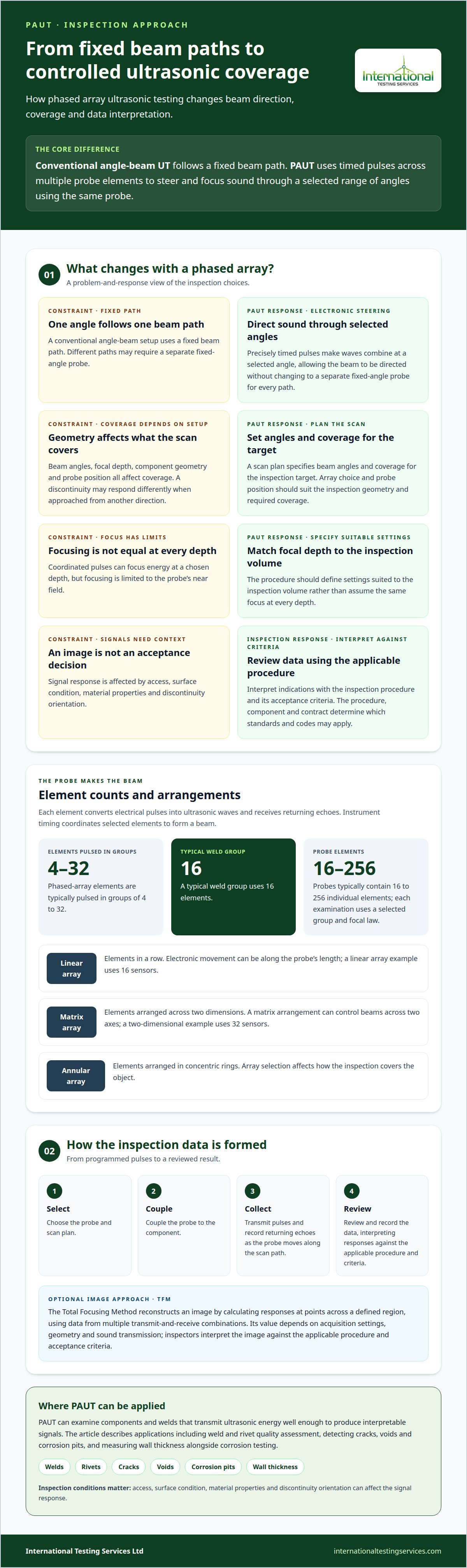
The key difference is control of the sound beam. Phased array ultrasonic testing (PAUT) uses multiple probe elements, with precisely timed pulses to steer and focus ultrasound through a component. A conventional angle-beam setup follows a fixed beam path, while PAUT can direct the beam through a selected range of angles using the same probe.
Both phased array ultrasonic testing (PAUT) and conventional ultrasonic testing use reflected sound to examine materials, but they generate and present signals differently. Understanding the distinction helps engineers choose an inspection approach suited to the required coverage and interpret the resulting indications.
This article explains how PAUT probe elements work, how electronic timing creates a sector scan, and how inspectors interpret the data. It also compares PAUT with conventional ultrasonic testing in practical terms, including coverage, setup, and weld examination. You’ll learn what the method can show and when conventional UT remains relevant.
Key Takeaways
- Understand how timed pulses from multiple probe elements steer and focus an ultrasonic beam, supporting inspection from different angles.
- Learn how element arrangements affect beam movement and the coverage produced during an examination.
- See how sector scanning sweeps the beam through a selected range of angles and presents the responses for interpretation.
- Compare the flexibility of phased array inspection with the fixed beam paths used in conventional ultrasonic testing, and consider what each method can contribute to an inspection plan.
- Identify when International Testing Services’ Phased Array Inspection may support weld and component examination, alongside other relevant inspection methods.
What is Phased Array Ultrasonic Testing (PAUT) and How Does it Work?
PAUT uses multiple probe elements to control an ultrasonic beam electronically. Timed pulses steer and focus sound through a component, enabling examination from different angles.
Standards and codes: ASME, API, ISO, and ASTM documents may govern PAUT, depending on the contract, component, and examination procedure. Applicable standards may address ultrasonic examination methods for welds and phased-array techniques. ASTM E2700 (2012) addresses contact ultrasonic testing of welds using phased arrays. ISO/WD 13588 is a listed work-draft document for semi-automated phased-array weld testing; prEN 16018 is a CEN terminology document.
Technician qualification in the United States depends on the applicable code, employer qualification system, and assigned inspection duties. Training and certification requirements relate to the technique, equipment, and examination scope. Anyone interpreting phased-array data must also understand the inspection procedure and its acceptance criteria.
Electronic Beam Steering and Depth Focusing
Electronic steering changes the beam direction by adjusting pulse timing across probe elements. Delays cause sound waves to combine at a selected angle, while coordinated pulses focus energy at a chosen depth. During weld examination, this can direct sound toward different regions without changing to a separate fixed-angle probe for every path.
Coverage depends on beam angles, focal depth, component geometry, and probe position. Focusing is limited to the probe’s near field, so the procedure must specify settings suited to the inspection volume rather than assume equal focus at every depth.
Total Focusing Method
The Total Focusing Method (TFM) reconstructs an image by focusing signals at points across a defined region. It processes data from multiple transmit-and-receive combinations to calculate the response at each image point. The result is a focused display across the selected area, rather than one based on a single focal point.
TFM can help show the position and shape of complex indications. Its value depends on acquisition settings, geometry, and sound transmission. Inspectors interpret the image against the applicable procedure and acceptance criteria.
Inspectable Materials, Welds, and Defects
PAUT can examine components and welds that transmit ultrasonic energy well enough to produce interpretable signals. Applications include assessing weld and rivet quality, and detecting cracks, voids, and corrosion pits. It can also be used to measure wall thickness alongside corrosion testing.
Access, surface condition, material properties, and discontinuity orientation affect the signal response. A scan plan sets beam angles and coverage for the target. A discontinuity may produce a different response when approached from another direction.
Safety: PAUT does not use ionising radiation. Inspectors must still manage site hazards, including restricted access, electrical equipment, and couplant handling. Cable routing and equipment placement also require care near moving plant or in confined work areas.
Phased array probe elements and arrangements
A phased array probe combines multiple small transducer elements in one assembly. Their arrangement and firing sequence determine how the instrument forms beams and collects inspection data.
A typical system comprises a probe, phased-array instrument, connecting cables, data-processing software, and display. Inspection usually involves selecting the probe and scan plan, coupling the probe to the component, collecting signals, and reviewing and recording the resulting data.
Probe Elements and Beam Formation
Each probe element converts electrical pulses into ultrasonic waves and receives returning echoes. The instrument controls the timing across selected elements, causing their sound waves to combine into a beam. Phased array elements are typically pulsed in groups of 4 to 32, while a typical weld group uses 16 elements. This coordination supports controlled beam formation during inspections.
The number and grouping of elements influence the available beam patterns and coverage. For example, an instrument can pulse successive element groups to move a beam electronically across the probe face. The resulting imaging data helps the inspector relate indications to their position within the component.
Array Types and Probe Construction
A linear array places elements in a row, while a matrix array arranges elements across two dimensions. A linear array example uses 16 sensors; a two-dimensional matrix example uses 32. An annular array arranges elements in concentric rings. These configurations provide different ways to direct sound and collect data, so array selection affects how an inspection covers the object.
The probe also has an element assembly and housing that holds the array against the test surface. A linear probe can support electronic movement along its length, while a matrix arrangement can control beams across two axes. The inspection geometry and required coverage help determine the suitable arrangement.
Probe Operation
During operation, the instrument applies programmed timing to transmit pulses and then records the returning echoes. It can fire successive groups of elements, shifting the active aperture along a linear probe. Phased array probes typically contain 16 to 256 individual elements, although each examination uses a selected group and focal law suited to its scan plan.
During weld examination, the probe moves along the scan path as the instrument records responses. The system associates each response with the probe position and beam setting, creating data for interpretation. These advantages depend on consistent probe contact and a setup suited to the component’s geometry.
Sector scanning
Sectorial scanning steers an ultrasonic beam through a selected range of angles from a probe position. For example, a weld scan can sweep through 40° to 70° shear angles. Each angle provides a different sound path through the material, supporting examination of regions that a single fixed beam may not reach effectively. The display combines responses across the defined sector.
The instrument creates each beam angle by applying electronic delays to the array elements. Changing those delay laws changes the wavefront direction, then the probe receives reflected signals for analysis. A simulated sector scan can use a 32-element linear array across angles from -30 to +30 degrees. This example shows how one probe position can generate a fan of beam paths for coverage assessment.
In a real-time sector scan, the instrument presents responses from the selected angles as an S-scan image. A real-time example uses a 64-element linear array; its displayed A-scan cursor identifies a signal at 49 degrees. The cursor connects an image location with the signal received at that beam angle. This view helps inspectors relate a response to its position and direction.
In manual scanning, the inspector moves the probe along the examination surface while maintaining suitable contact. At each position, electronic steering supplies the selected angles and the instrument records the signals. A weld scan can combine movement along the weld with a sector sweep through the inspection volume. Consistent movement and positioning help achieve interpretable coverage.
Automated or mechanically assisted scanning uses a system to move the probe along a planned path. The array creates the sector electronically, while the mechanical system records data at successive probe positions. The resulting dataset links position with beam angle. Repeatable coverage depends on controlling the scan path, coupling, and component geometry.
Not every sector-scan angle is equally useful. Weld geometry, access, material response, and the orientation of a possible discontinuity all affect which beam paths help detect it. The scan plan defines the sector and probe position relative to the target. Inspectors assess signal patterns across angles rather than treating one bright indication as a complete evaluation.
For interpretation, the S-scan gives an overview, while individual A-scans retain signal detail at selected angles. Comparing the views can help distinguish a relevant response from geometry-related echoes. Recording probe position alongside sector data during manual or mechanical scanning preserves the link between an indication and its location, supporting consistent evaluation of the inspected area.
Advantages over conventional ultrasonic testing
Conventional ultrasonic testing and phased array ultrasonic testing share the same principle: sound enters a component, and reflected signals help identify discontinuities. The difference is how the beam is controlled. A conventional single-element probe follows a selected beam path, while PAUT can use electronic steering to examine material from multiple angles. That ability can improve coverage where weld geometry or access limits probe placement.
PAUT may reduce probe changes and repeated setups. One phased-array probe can replace multiple conventional probes, simplifying procedures that would otherwise need separate probes, calibrations, and setups. For example, programmed beam angles from one array can examine different regions of a weld. The procedure still requires suitable calibration and defined acceptance criteria.
Electronic scanning can reduce the need for mechanical probe movement. A phased-array system moves the active beam across the probe electronically, whereas a single-probe mechanical system relies on physical movement to build coverage. Component coverage can typically be an order of magnitude faster with a phased-array system than with a single-probe mechanical system. Actual inspection time also depends on access, geometry, scan plan, and data review.
PAUT can present results as encoded images rather than isolated readings alone. An S-scan, for example, shows responses across a range of angles, helping the inspector assess indication locations relative to a weld profile. Conventional UT remains useful when a defined fixed path and direct signal interpretation meet the inspection requirement. The reference standard and acceptance criteria govern how either method is applied.
Accuracy and reliability: PAUT can detect and image discontinuities such as cracks, voids, and corrosion pits, but flaw sizing is not automatic or exact. Results depend on calibration, beam direction, material properties, surface condition, procedure, and interpretation. A flaw’s orientation relative to the sound beam can affect its response, so the scan plan and reference reflectors matter.
Neither method is destructive: both use ultrasonic energy to assess material without cutting it or removing a test sample. PAUT’s more complex equipment and probes must be matched to the inspection task. A complex weld requiring coverage from several angles may benefit from electronic steering, while conventional UT may be adequate for a straightforward examination with suitable access.
Choose the method according to the component, target discontinuities, required coverage, and governing procedure. PAUT offers flexible beam control and imaging, while conventional UT can focus on a selected path. A qualified inspection procedure defines how indications are recorded and assessed, so the method supports the required engineering decision.
How phased array ultrasonic testing works
An examination turns a written inspection requirement into a defined data-collection plan. The procedure identifies the component area, intended coverage, and records needed for assessment. The inspector configures the instrument to collect data for that scope, linking the physical scan to the engineering decision it must support.
Before data collection, component geometry and accessible surfaces inform probe placement and scan direction. The operator establishes a reference position so responses can be related to locations on the component. For a weld, the scan is organized around the weld and required examination area, rather than treating the displayed data as an isolated image.
During scanning, the instrument follows the inspection setup and records ultrasonic responses. Probe movement and data collection must stay coordinated so each reading has a meaningful location within the scan. The procedure specifies how the instrument captures and stores examination data, providing a traceable basis for reviewing indicated areas.
After data collection, the inspector reviews responses in relation to the component and scan path. Relevant signals are assessed under the applicable procedure, considering their location and consistency in the collected data. This review distinguishes an indication requiring evaluation from an unexplained display feature. The instrument presents evidence; the inspection criteria govern its interpretation.
For a weld, the examination record should link each reported indication to the weld region and the scan data supporting its assessment. This helps reviewers understand where the indication was observed and how it was evaluated. Clear records also maintain continuity when results inform repair, acceptance, or subsequent examination decisions.
Data quality depends on the relationship between the planned scope, actual probe movement, and captured responses. If the probe does not cover the intended area, the resulting record cannot fully represent it. The operator follows the procedure’s positioning and acquisition requirements, and interpretation remains tied to the specified acceptance criteria.
Treat the examination as a controlled sequence: define coverage, configure the instrument, acquire position-linked data, and evaluate indications against the governing procedure. Each stage supports the next. An instrument alone cannot establish whether a component meets its acceptance requirements; that decision depends on the agreed examination scope and documented assessment.
That chain also depends on how the array is timed and focused. Phased array time-delay circuits must be accurate to around 2 ns to provide the required phasing accuracy. The focal law governs the acoustic sensitivity field used during the search: ASTM E-1316 defines a focal law as the entire set of hardware and software parameters affecting a phased array search unit’s acoustic sensitivity field. These settings shape what the instrument can detect and how responses are represented, so they belong in a controlled examination setup, not merely as display choices.
A phased array can capture hundreds of signals at once to help characterize defects. Reviewing the responses alongside their positions gives the inspector a basis for assessing indications within the defined scope. Consistent setup and traceable data collection support meaningful evaluation and later review.
International Testing Services: Phased Array Inspection
International Testing Services Ltd provides Phased Array Inspection for projects requiring ultrasonic examination of welds or components. The service suits inspection plans that call for electronic beam control, encoded coverage, or recorded data for technical review.
Where the scope calls for complementary methods, Ultrasonic Inspection and TOFD Inspection can also support the assessment. Magnetic Particle Inspection may suit relevant surface and near-surface discontinuities. Method selection should reflect the component, target, access conditions, and applicable inspection requirements.
For a PAUT project, include the component details, inspection location, target areas, and governing specification in your enquiry. Contact International Testing Services Ltd to discuss the requirement and next steps.
Plan the Examination Around the Engineering Decision
Before inspection begins, define the decision the results must support. The component, examination area, access conditions, governing specification, and required records shape the scope. Aligning these details early helps establish a procedure that addresses the relevant acceptance criteria and produces usable inspection records.
For an array-based ultrasonic examination, the inspection plan should link the target area with suitable probe positioning, coverage, and data review. International Testing Services Ltd provides Phased Array Inspection, TOFD Inspection, and Ultrasonic Inspection. The component and examination requirement guide the choice of method and the agreed scope.
Bring relevant drawings, specifications, and scope details into that discussion. Contact International Testing Services Ltd to discuss your inspection requirements and identify a suitable next step. A clear scope gives your project team a sound basis for planning the examination and moving forward with confidence.
Frequently Asked Questions
How does it work?
Phased array ultrasonic testing uses controlled sound pulses to examine a component and record reflected signals. For a weld, the procedure defines inspection zones and records responses against probe position, allowing the data to be reviewed against the weld geometry. The inspector assesses relevant indications using the applicable procedure and acceptance criteria. This recorded examination supports traceability when findings require technical review.
Where Are Phased Array Systems Used?
Phased array systems are used in construction, pipelines, and power generation, as well as for assessing welds and rivets. Other applications include examining rolling stock wheels and axles, where the target and access conditions determine the scan arrangement. An engineering team might specify the method for a pipeline weld or power-generation component when internal examination is required. The inspection scope governs its use.
What are the advantages and limitations of PAUT compared with conventional ultrasonic testing and radiography?
Compared with conventional ultrasonic testing, PAUT uses an array to collect data across multiple beam paths, while conventional UT may suit a simpler examination with a fixed path. PAUT equipment and probes are more complex. Unlike radiography, PAUT does not use radiation, so the site controls differ. Selection still depends on the component, access, required evidence, and applicable acceptance criteria.
How much does phased array ultrasonic testing equipment and inspection service cost in the United States?
No general U.S. price is provided. PAUT equipment and probes are more complex and expensive than conventional single-element systems, although one described comparison found a portable phased array system cost about one-third as much as a conventional immersion scanning system.


