

Finding a defect before production scales up can prevent a recurring quality issue. NDT for manufacturing quality control examines materials and components without damaging them, allowing them to remain usable after inspection. It can identify surface and internal defects, including cracks, voids and corrosion, while there is still time to use the findings to improve the manufacturing process.
Quality control involves more than checking finished products. Inspection can assess incoming materials, verify weld integrity and reveal recurring issues that may call for changes to production or design. Choose a method according to the material, component and defect being assessed.
This article explains non-destructive testing and how methods such as ultrasonic testing, phased array inspection, TOFD, magnetic particle inspection and liquid penetrant inspection are used in manufacturing. It also covers how inspections at different production stages can support early defect detection, process control and product development, and how findings can inform decisions about quality and reliability.
Key Takeaways
- Plan inspections for incoming materials and prefabricated components so defects can be identified before they move further through production.
- Understand how radiographic testing reveals internal features and why method selection depends on the material and the inspection objective.
- Use inspection findings to identify recurring defects and inform process adjustments before they affect larger production runs.
- Match inspection methods to the component: welds, castings, pipes and composites present different defect-detection requirements.
- Learn how phased array, TOFD, ultrasonic and magnetic particle inspection can support manufacturing quality decisions.
What’s The Role of NDT Inspection in Product Development?
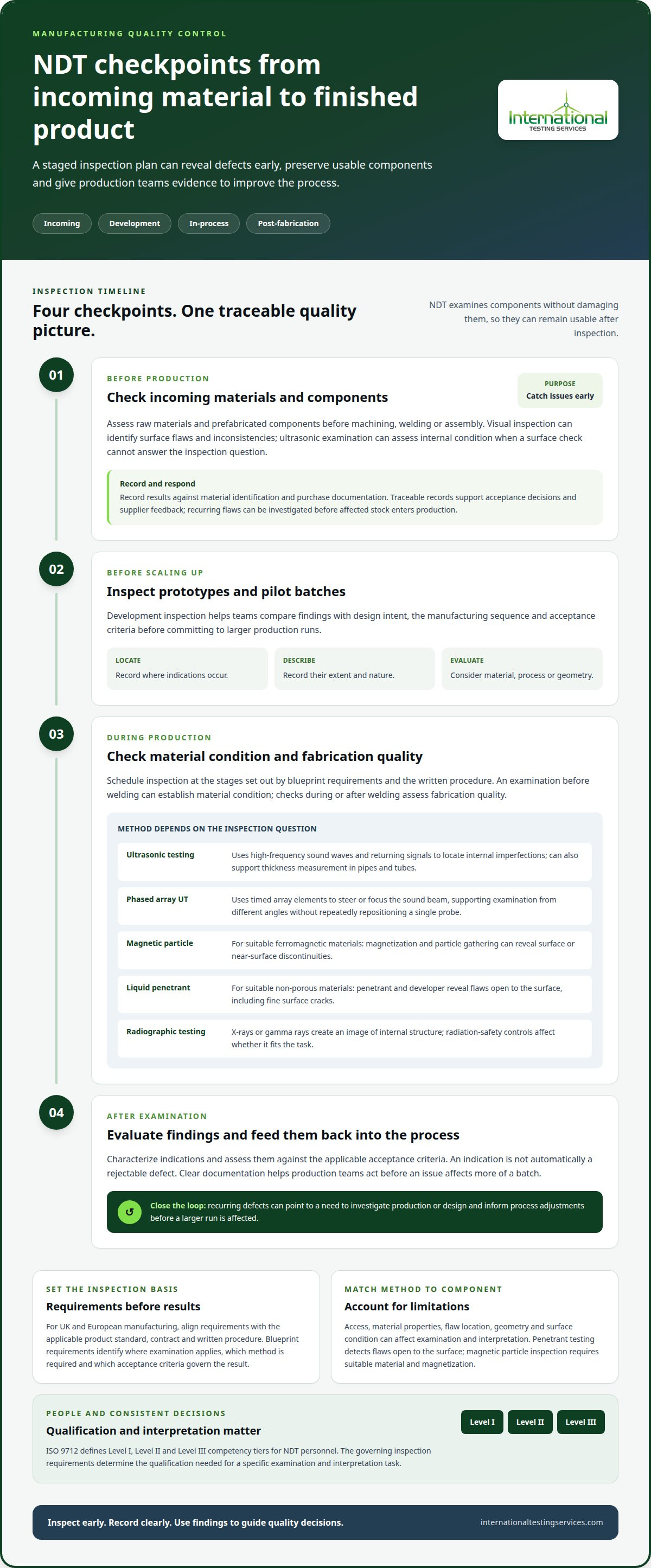
Inspection can inform product decisions before a design enters full production. Incoming checks, development trials and blueprint requirements help relate material condition to manufacturing quality.
Incoming Material and Component Checks
Incoming inspection assesses raw materials and prefabricated components before machining, welding or assembly. Visual inspection can identify surface flaws, discontinuities and inconsistencies in steel plate or cast components. Ultrasonic examination can assess internal condition when a surface check cannot answer the inspection question.
Record results against material identification and purchase documentation, and report indications that require evaluation. Traceable records support acceptance decisions and supplier feedback. If incoming material shows recurring flaws, engineers can investigate the source before affected stock enters production. For an aerospace component or fabricated assembly, early checks can also help distinguish a material issue from a defect introduced during manufacturing.
Inspection Across Development and Manufacturing
Development inspection examines prototypes and pilot batches before a manufacturer commits to larger production runs. Teams can compare findings with design intent, the manufacturing sequence and acceptance criteria. Pilot inspections can also help characterize indications by recording their location, extent and nature, supporting evaluation of whether they relate to the material, process or geometry.
Inspections can be scheduled at incoming, in-process and post-fabrication stages. For example, examination before welding can establish material condition, while checks during or after welding assess fabrication quality. Blueprint requirements and inspection symbols specify where examination applies, which method is required and which acceptance criteria govern the result. Clear documentation helps production teams act on findings before an issue affects more of a batch.
Fluorescent Penetrant and Magnetic Particle Methods
Fluorescent penetrant inspection uses penetrant and ultraviolet light to reveal surface-breaking flaws in suitable non-porous materials. The penetrant enters surface openings; after excess liquid is removed, developer draws out the remaining penetrant for examination. This method can reveal fine surface cracks that visual inspection may miss.
Magnetic particle inspection is used primarily on ferromagnetic materials. The component is magnetized, and particles gather where flux leakage indicates a surface or near-surface discontinuity. Both methods have limits: penetrant testing detects flaws open to the surface, while magnetic particle inspection requires suitable material and magnetization. Geometry and surface condition can also produce indications that need evaluation against acceptance criteria.
Standards, Qualifications, and Method Limitations
For UK and European manufacturing, inspection requirements should align with the applicable product standard, contract and written procedure. ISO 9712 defines Level I, Level II and Level III competency tiers for NDT personnel. The governing inspection requirements determine the qualification needed for a specific examination and interpretation task.
Method limitations include access, material properties and flaw location. Radiographic examination requires radiation-safety controls. Other methods can produce indications that must be evaluated to distinguish relevant flaws from geometry or surface effects. Selecting a method to match the blueprint, then recording and characterizing indications, supports consistent decisions against the applicable acceptance criteria.
What Is NDT (Non-Destructive Testing)?
Non-destructive testing examines materials or components without damaging them, so they can remain usable after inspection. Unlike destructive testing, which tests a sample to failure, NDT provides evidence about integrity while preserving the component.
Radiographic Testing
Radiographic testing uses X-rays or gamma rays to create an image of a component’s internal structure. Differences in how materials absorb radiation can reveal internal features that surface examination cannot show.
For a weld, the resulting image can help identify internal discontinuities such as porosity or inclusions. Assess the image against the applicable acceptance criteria: an indication is not automatically a rejectable defect. Radiation controls and access to suitable inspection arrangements also affect whether this method fits a production task. Radiography is useful when the inspection objective requires a record of internal structure, but suitability depends on component geometry, material and required coverage.
Ultrasonic and Phased Array Testing
Ultrasonic testing sends high-frequency sound waves into a material and analyses the returning signals to locate internal imperfections. It can detect features such as cracks, voids and inclusions in metals and composites, and can also support thickness measurement in pipes and tubes.
Phased array ultrasonic testing uses an array of elements activated with controlled timing. This allows the sound beam to be steered or focused, supporting examination from different angles without repeatedly repositioning a single probe. The resulting data helps locate and characterize indications within the defined inspection area. Surface condition, geometry, material structure and access can affect examination and interpretation, so the procedure must suit the component and its inspection requirements.
Liquid Penetrant Testing
Liquid penetrant testing reveals flaws that break the surface of non-porous materials, including metals, ceramics and plastics. The process involves applying penetrant to a cleaned surface, allowing it to enter openings, removing excess liquid and applying developer to draw the penetrant back out.
Visible or fluorescent indications can show where a surface discontinuity exists. Examine fluorescent penetrant under ultraviolet light and visible dye under suitable lighting. This method does not reveal defects buried beneath an intact surface, so it cannot replace a method selected for internal examination. Cleaning and surface preparation matter: contaminants can block openings or create background indications that complicate evaluation.
Visual Testing
Visual testing examines accessible surfaces directly, with or without aids such as lighting, mirrors or magnification. It can identify visible damage, surface discontinuities, corrosion and changes in weld profile before more targeted testing is considered.
Its value depends on access, surface condition and the inspector’s ability to see the area under suitable viewing conditions. Visual testing cannot establish that hidden flaws are absent. For example, an external examination of a pipe may reveal surface corrosion but cannot determine the internal wall condition by sight alone. At incoming inspection or during fabrication, documented visual findings can guide whether further examination is needed and which method can answer the remaining question.
Manufacturing process control and early defect detection
Planned inspection points help manufacturers identify defects before affected components move on to later operations. Recorded results can inform production decisions, supplier feedback and process improvements.
Surface Flaws and Thickness Changes
Surface and thickness examinations can identify changes that may indicate manufacturing defects, wear or corrosion. Visual checks can reveal visible flaws, while liquid penetrant testing identifies defects that break the surface of suitable non-porous materials.
For conductive materials, electromagnetic testing can detect surface and near-surface discontinuities. Ultrasonic testing can measure wall thickness in pipes and tubes and detect internal flaws. Comparing measurements at defined inspection locations helps identify local thinning that might otherwise go unnoticed during production.
Inspection findings become useful evidence for process control when teams record the component, location, method and result. For example, repeated surface cracks in parts from the same operation can prompt an investigation of that manufacturing stage. A penetrant indication still needs evaluation against the applicable acceptance criteria.
Stress, Strain, and Weld Imperfections
NDT findings can help identify defects that may affect component integrity and areas where stress or strain may be a concern. The results support investigation, but should not be treated as a direct measurement of every stress condition.
Radiographic and ultrasonic testing can examine welds for internal imperfections such as cracks, porosity and inclusions. Visual inspection assesses accessible weld surfaces, while magnetic particle testing can reveal surface and near-surface cracks in ferromagnetic materials. Select the method according to the material and inspection objective.
To support corrective action, connect each indication to its weld, production stage and inspection record. Comparing findings across a production run helps distinguish an isolated result from a recurring pattern. Engineers can then review relevant process settings or fabrication steps before more components are affected.
Inspection Data in Production Control
Automated inspection data can enter production quality systems through defined capture fields, hand-offs and review steps. Manufacturers can align inspection workflows with station layouts and production takt time, then link results to component identification, operation and disposition.
Trend analysis can reveal repeated defects and support supplier feedback. Connecting findings with machining, additive manufacturing, assembly and supplier decisions helps teams investigate the origin of a recurring issue rather than treating each indication in isolation. Clear acceptance criteria also help production staff determine whether a finding needs further evaluation or corrective action.
For plastics, high-resolution computed tomography can detect contraction cavities, blisters, weld lines and cracks. Three-dimensional images can also show characteristics such as filler distribution and fibre orientation. Comparing these results with the intended component design can support flaw analysis and process optimisation, particularly where surface examination cannot reach internal features.
Need Manufacturing Inspection and NDT?
NDT can examine manufactured components during production and later in service, using methods matched to the material and inspection objective. Manufacturers choose methods by considering material properties, defect location and type, component geometry, access, required coverage and production volume.
Applications Across Components and Materials
Different components require different inspection approaches. Radiographic testing and ultrasonic testing can examine welds for internal imperfections, while visual inspection assesses accessible surfaces. Ultrasonic testing can also measure pipe wall thickness and locate internal flaws, supporting checks on pipes and tubes.
For castings, inspection after production or secondary processing can help identify material discontinuities before components enter assembly. Composite materials present different challenges: ultrasonic testing can detect delamination, voids and other internal defects. Penetrant testing suits surface-breaking flaws on non-porous materials, not hidden defects beneath an intact surface.
These distinctions matter in aerospace, aviation and automotive production, where component material, geometry and intended function influence the inspection plan. A method that reveals an internal weld imperfection may not answer a question about composite delamination or a surface crack.
Inspection Across the Component Life Cycle
NDT can be used before production, during fabrication, after manufacture and while a component remains in service. Manufacturers may inspect castings, forgings and extrusions after production or secondary processing, then examine components again after repair or modification.
The inspection objective changes at each stage. Incoming checks assess supplied material; in-process examinations can detect fabrication issues before subsequent operations; post-repair inspection evaluates completed work. For components in demanding environments, periodic in-service inspection can help assess their condition and identify damage that develops during operation.
In aerospace and aviation manufacturing, inspection planning must reflect the component’s material, design and inspection requirements. Prototype examination can provide evidence for design evaluation, while production inspection assesses manufactured items against defined criteria. Lifecycle records help teams relate later findings to earlier examinations and manufacturing stages.
Defect Detection in Manufactured Components
Defects can include cracks, porosity, inclusions, corrosion, wall-thickness changes and composite delamination. Their location matters: surface-breaking flaws require a method capable of examining the surface, while internal imperfections require a method that can examine the material beneath it.
For example, ultrasonic examination can locate internal flaws in a pipe, while visual inspection can record visible surface condition. Radiographic testing can produce an image of internal weld features. Interpret results against the inspection criteria: an indication is evidence to evaluate, not automatically a failure.
Inspection records should connect each finding to the component, examination area, method and disposition. Comparing results across production batches can help identify recurring defects and focus process investigations. In aerospace, automotive or general fabrication, that traceability supports decisions about rework, acceptance and whether a manufacturing step needs review.
NDT in manufacturing quality control
NDT supports manufacturing quality control when inspection methods, acceptance criteria and production records work as one system. A robust plan defines the evidence needed at each production stage and how teams will use it.
Comparing Manufacturing NDT Methods
Each NDT method answers a different inspection question, so selection starts with the material and potential defect. Visual testing examines accessible surfaces; liquid penetrant testing reveals surface-breaking flaws on suitable non-porous materials. Magnetic particle inspection detects surface and near-surface discontinuities in ferromagnetic materials.
Ultrasonic testing examines internal features and can measure material thickness. Radiographic testing produces images of internal structure, while electromagnetic techniques can identify surface or near-surface flaws in conductive materials. Component geometry, access, surface condition and required coverage all influence method selection.
For example, magnetic particle inspection can assess a ferromagnetic weld for surface cracks, while liquid penetrant inspection can reveal surface-breaking flaws on a suitable non-porous part. Neither method provides evidence about every internal condition. Match the examination to the defect concern and applicable acceptance criteria.
Implementing a Quality Control Plan
Start by identifying component characteristics, likely defects and the production stages where findings can inform corrective action. Select methods according to material, defect location, geometry, access and required coverage. This makes the inspection plan responsive to the component and process, rather than a routine examination without a defined objective.
Define the examination procedure, acceptance criteria, indication evaluation and documentation requirements before routine production. The Center for Manufacturing Advancement describes these as elements of NDT procedure development. A pilot inspection can test whether the selected method and workflow produce useful results under production conditions.
Manufacturers can strengthen implementation by:
- Linking each inspection point to a component, process stage and acceptance requirement.
- Defining how indications are recorded, evaluated and escalated for disposition.
- Connecting results with machining, assembly, supplier and production records.
- Reviewing recurring findings to identify trends and direct corrective action.
Automated inspection data can feed into quality systems when capture fields, station hand-offs and review responsibilities are defined. Records should identify the inspected area, method, indication and disposition. Trend analysis can distinguish an isolated finding from a recurring issue linked to a process or supplier.
For manufacturing plans involving surface examination, contact International Testing Services Ltd about magnetic particle or liquid penetrant inspection in relation to the material and defect being assessed. Clear criteria and traceable records help inspection findings support consistent production decisions.
International Testing Services Ltd: Phased Array Inspection
International Testing Services Ltd provides Phased Array Inspection for manufacturing teams requiring ultrasonic examination. This service can be relevant when the inspection scope concerns welds or components and the required coverage informs method selection.
TOFD Inspection and Ultrasonic Inspection are also available for manufacturing examination requirements. The appropriate method depends on the component, material and inspection objective, as well as the applicable acceptance criteria.
To discuss an inspection scope for your components, contact International Testing Services Ltd.
Make Inspection Part of the Production Decision
Set a clear inspection objective for each component and production stage. Define what the examination must establish, which acceptance criteria apply and how findings will inform the next manufacturing decision. This gives quality and engineering teams a consistent basis for planning inspection and reviewing results.
A considered approach to NDT for manufacturing quality control connects inspection evidence with decisions about components, suppliers and production methods. Match the examination method to the material, geometry and defect concern, then make the necessary information available to those responsible for disposition.
International Testing Services Ltd offers Phased Array Inspection, TOFD Inspection and Ultrasonic Inspection for relevant manufacturing requirements. Contact International Testing Services Ltd to discuss an inspection scope for your components and quality objectives. A defined scope provides a constructive starting point for your next production decision.
Frequently Asked Questions
How Is NDT Performed and How Long Does It Take?
NDT starts by defining the component, examination area, method and acceptance criteria. A technician prepares the surface or equipment, performs the examination, evaluates indications and records the result. A simple visual inspection may take minutes, while thorough ultrasonic or radiographic examinations may take several hours or even days. Component access, geometry, preparation, inspection coverage and reporting requirements affect the overall duration.
What Is NDT?
NDT examines a material, component or structure without damaging it during testing. It differs from destructive testing, where a sample is deliberately damaged or tested to failure. For example, a manufacturer can examine a weld using ultrasonic testing while retaining the part for its intended use. The selected method determines what evidence the examination can provide, such as surface condition or internal features.
When Is NDT Inspection Not Necessary?
NDT may be unnecessary for a non-critical, low-cost product when safety, performance and reliability concerns are minimal and its intended use avoids harsh conditions. A simple item with visible features may need only visual checks if they address its quality requirements. The decision should account for product function, failure consequences, material behaviour and applicable specifications, rather than applying the same examination scope to every manufactured item.
When Is NDT Testing Required?
NDT is required when an applicable code, product specification, contract or approved inspection plan calls for it. Requirements can depend on component type, service conditions, material and the consequences of a defect. For pressure equipment or a welded assembly, project documents may define examination methods and acceptance criteria. Quality teams should use those governing requirements to establish the inspection scope and record the basis for acceptance.
When Should NDT Inspection Be Done?
Schedule inspection when its findings can still guide a manufacturing or maintenance decision. Incoming material checks can keep questionable stock out of production; in-process examinations can identify issues before later operations conceal or complicate them. Post-fabrication checks assess the completed component, while inspection after repair evaluates the affected area. In-service examinations can support condition assessment when operating demands or inspection plans make them relevant.
What Is Nondestructive Testing (NDT) in Manufacturing Quality Control?
NDT in manufacturing quality control is the planned use of non-damaging examinations to assess components against defined requirements. It links inspection results to decisions such as accepting a part, investigating an indication or reviewing a production step. For example, recurring findings across a batch can prompt an examination of a process or supplier record. Its value lies in consistent criteria and traceable results, not simply in collecting inspection data.
What Defects Can Visual, Ultrasonic, Radiographic, Magnetic Particle, and Dye Penetrant Testing Detect?
Visual testing identifies visible surface flaws; ultrasonic testing can detect internal cracks, voids and inclusions. Radiographic testing can reveal internal features such as porosity or inclusions. Magnetic particle testing finds surface and near-surface discontinuities in ferromagnetic materials, while dye penetrant testing reveals flaws open to the surface on suitable non-porous materials. Each method has limits, so defect location, material and component geometry guide selection.


