

A clean-looking surface is not proof that a part is defect-free. Surface defect inspection detects external flaws by capturing 2D or 3D image data under controlled illumination, then processing it for contrast, edge patterns and geometric irregularities or comparing it with reference images. It classifies surface condition; 3D inspection checks geometry and dimensions, while non-destructive testing can extend examination into a part without damaging it.
Image comparison can reveal scratches, cracks, contamination or coating defects by highlighting differences from an accepted reference. Reliable interpretation depends on the inspection objective and how the image data relates to the part’s material and surface.
This article explains how cameras, lighting and image-processing methods identify surface defects across different materials. It also clarifies where reference comparisons fit, how surface inspection differs from 3D measurement, and when non-destructive testing can assess concerns below the visible surface.
Key Takeaways
- Controlled lighting and camera data help reveal external flaws, while the inspection setup should reflect the material and defect type.
- Comparing captured images with a suitable reference can highlight irregularities, but reliable decisions depend on clear criteria and correctly configured parameters.
- Inspection approaches vary across metals, glass, ceramics, wood, textiles and films; surface characteristics shape how defects appear in the data.
- Separate surface assessment from dimensional checks: 3D inspection evaluates geometry, while non-destructive testing can examine internal material condition without damage.
- Position production-line inspection around the process risk, and define how findings will inform part rejection or further assessment.
How does surface defect detection work?
Surface defect inspection examines a part’s exterior for flaws and deviations, rather than measuring its overall dimensions. In production, cameras and sensors capture the surface so operators or software can identify defects such as scratches, cracks and coating irregularities.
Limits of Manual and Traditional Inspection
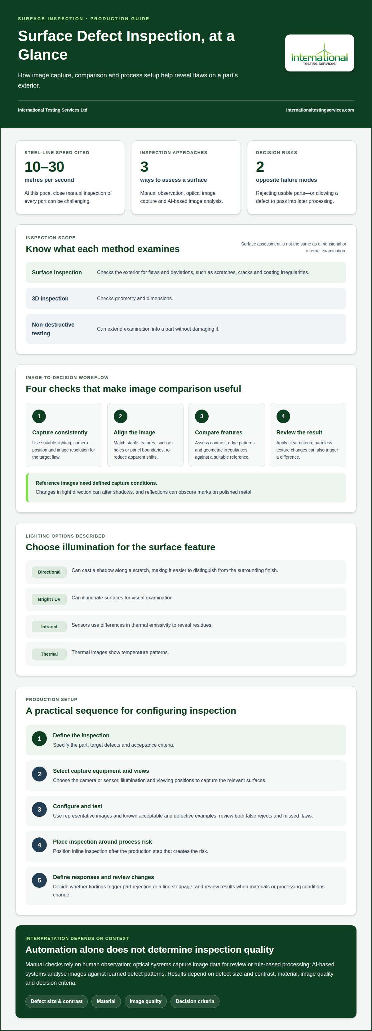
Manual inspection relies on an operator’s visual assessment under the available lighting and viewing conditions. On steel lines running at 10-30 metres per second, inspecting every part closely can be challenging. Repeated checks of automotive panels or machined parts can also make small differences harder to distinguish from normal surface variation.
Traditional automated systems apply fixed rules to images, but their decisions depend on suitable parameters. A threshold set too strictly may flag acceptable texture as a defect; one set too loosely may miss a fine crack. False rejects can remove usable components from production, while missed defects can pass into later processing.
Camera and Sensor Based Inspection
Automated camera-based systems capture external surfaces and send image data to a computer for processing. Several cameras can record different perspectives in one operation, helping cover complex forms such as vehicle body panels or housings. Controlled illumination makes features such as scratches easier to distinguish from the surrounding finish.
Directional lighting can cast a shadow along a scratch, increasing its contrast. Bright or ultraviolet light can also illuminate surfaces for visual examination. Infrared sensors use differences in thermal emissivity to reveal residues, while thermal images show temperature patterns. These methods support repeatable review, but lighting, camera position and image resolution must suit the target flaw.
Comparing Inspection Methods and Accuracy
Manual, optical and AI-based inspection differ in how they assess a surface. Manual checks rely on human observation; optical systems capture image data for review or rule-based processing; AI-based systems analyse images against learned defect patterns. No single accuracy figure applies to every method: results depend on defect size and contrast, material, image quality and decision criteria.
For example, a camera may identify a paint scratch on an automotive panel by detecting differences in edges and contrast. AI can classify image patterns, but its output still depends on representative examples and suitable thresholds. Consistent image capture and evaluation, not automation alone, drives improvement.
System Selection and Process Setup
Set up inspection by first defining the part, target defects and acceptance criteria. Then choose the camera or sensor, illumination and viewing positions needed to capture the relevant surfaces. For circuit boards, targets may include solder defects or contamination; for rolled steel, they may include cracks, scratches or coating variation.
Then capture representative images and configure the processing rules or AI classification criteria. Test the setup against known acceptable and defective examples, reviewing false rejects as well as missed flaws. Finally, position inline inspection after the production step that creates the risk. Decide how findings will trigger part rejection or a line stoppage, and review results when materials or processing conditions change.
Image processing and comparison with reference images
Image processing converts captured surface data into features that an inspection system can assess. In manufacturing, software may examine contrast differences, edge patterns and geometric irregularities. A dark line across a coated panel, for example, may indicate a scratch, while a changed edge may signal a chipped boundary. The system compares these features with reference images or target values.
A reference image represents an accepted surface under defined capture conditions. The inspection camera records a new image, and processing aligns it with the reference before identifying differences. Alignment matters: even a slight shift in a component’s position can make normal edges appear displaced. Image registration reduces this effect by matching stable features such as holes or panel boundaries.
Illumination must also remain consistent between the reference and the inspected part. Changes in light direction can alter shadows, while reflections can obscure a mark on polished metal. Image processing may normalise brightness or limit analysis to a defined region of interest. For a metal sheet, that region could exclude a fixture edge and focus on the usable surface.
The comparison method depends on the product and defect pattern. Direct pixel comparison can reveal a local contrast change, but may also respond to harmless texture variations. Edge analysis can help identify a crack or irregular boundary, while texture analysis can distinguish a repeated finish from an isolated mark. These approaches can be combined when the application requires separate checks for shape, surface pattern and contrast.
Reference comparison is also useful for patterned products. In semiconductor manufacturing, images from adjacent wafer dies can be compared to locate differences in repeated circuit patterns. A defect that appears in one die but not its neighbours becomes a candidate for review. This method relies on repeatable patterns; non-patterned surfaces need other forms of direct detection.
Continuous production introduces another consideration: the reference must represent the correct product and process state. A change in coating, finish or component design can make an older reference unsuitable. Controlled versioning helps ensure images are compared with the right target. Records should link each result to its part type, capture conditions and reference version.
Comparison results need defined decision criteria. A system may flag a region for review when its contrast or geometry differs from the accepted target. Engineers can then assess whether the change is a true defect or normal variation, such as grain differences in timber. Reviewing false alarms and missed defects helps refine image-processing parameters for the intended application.
Where image findings need to be considered alongside direct examination, visual inspection services can support a broader assessment. The key distinction remains clear: image comparison identifies deviations from a visual reference, while the inspection method must match the material, defect and production conditions.
Met
al, glass, ceramic, wood, textile, and foil inspection
Material properties affect how defects appear to a camera, so inspection systems need suitable lighting and image criteria. Reflective metal sheets, transparent glass bottles and woven textiles produce different patterns. Inspection methods must distinguish genuine flaws from ordinary surface variation.
In metal processing, rolled, forged and machined parts can be examined for cracks, scratches and inconsistent coating thickness. Directional lighting can make a scratch more visible by creating a shadow. On reflective surfaces, light position matters: glare can hide a mark or create a bright region that resembles one. Inspection criteria should account for the part’s finish and defects that affect its intended use.
Glass inspection presents a different challenge. Camera-based systems can examine transparent bottles for hairline cracks, liquid residues and contamination. Lighting must make the relevant feature visible against the glass and its background. Residue may appear as a local contrast change, while a crack can form a fine line. The setup must distinguish these indications from reflections and changes in bottle shape.
Ceramic inspection focuses on surface changes such as cracks, chips and irregularities in a glazed finish. Differences in colour or texture may indicate a defect, but can also reflect normal variation between pieces. For ceramic tiles, consistent illumination and defined assessment regions help compare edges, corners and central surfaces under similar conditions.
Wood requires inspection criteria suited to its natural grain. Knots and grain patterns are not automatically defects; their classification depends on the grading rules. In one example, two or more Dead_Knot defects result in a GRADE_C decision. Up to two minor defects with no moderate defects result in GRADE_B, while three or more moderate defects result in GRADE_C.
Textiles and other continuous materials, including latex, plastic films and cables, can be inspected by the metre. Consistent image capture is important across moving material. A camera can identify a local tear, mark or pattern change, while lighting helps distinguish surface damage from the regular weave or texture. Inspection systems must also account for changes in surface position as goods move through production.
Foil and sheet materials need checks for marks, surface irregularities and coating variation across broad, continuous areas. Pattern-recognition techniques have achieved 80% correct identification across five sheet-tinplate defect classes in one reported example. That result illustrates why the defect classes and evaluation criteria matter: an inspection system must indicate the relevant flaw without treating every surface variation as rejectable.
What types of surface defects can inspection detect?
Surface inspection can identify cracks, scratches, contamination, unevenness and coating defects. These categories describe visible conditions, not their cause or severity. For example, a linear mark on a component may be classified as a scratch, while a branching line may indicate a crack. Accurate classification helps teams apply consistent acceptance criteria across production batches.
Cracks appear as narrow lines, breaks or branching features on an exposed surface. Their visibility depends on orientation, contrast and surface finish. A crack running across a bright component may be difficult to distinguish from a reflection. Directional lighting can reveal its edge, while image processing can assess the line’s shape against the surrounding material.
Scratches and abrasion marks change the surface’s texture or reflectivity. On a coated panel, a shallow mark may alter reflected light without exposing the base material. A deeper scratch may interrupt the coating and create a more distinct boundary. Inspection criteria should distinguish acceptable handling marks from damage that affects the product’s specified finish.
Contamination includes particles, residue or foreign material on the surface. A camera may detect a particle through its contrast or shape, while infrared imaging can identify some residues through differences in thermal emissivity. On a clear plastic component, liquid residue can create an irregular area that differs from the clean surrounding surface.
Unevenness describes local changes in surface form or finish. A raised area on a machined part may alter its edge profile, while a depression can change reflected light. Surface inspection classifies visible irregularities; it does not replace dimensional measurement, which assesses size, form and position against nominal geometry.
Coating defects include inconsistent coverage, visible blemishes and changes in apparent thickness. On a painted component, a patch with different colour or gloss may indicate a finish issue. Image-based checks can locate the affected region, but interpretation depends on the product’s specified appearance and coating criteria.
Transparent materials present different indications. A hairline crack in a glass or plastic bottle may appear as a fine line, while residue may form a patch or streak. Lighting and viewing angle affect how clearly these features stand out. The system must distinguish defects from reflections, seams and expected changes in the material’s shape.
Not every material flaw is visible at the surface. Delaminations, internal discontinuities and material inconsistencies may require non-destructive testing rather than image comparison alone. Thermographic images may show local temperature deviations associated with subsurface conditions. This distinction matters: visual inspection identifies external indications, while other methods assess concerns within a component without damaging it.
How to choose a surface defect inspection system for a production line?
Select a system by matching the target defect, material and production step. A camera that identifies paint marks on an automotive panel may not detect contamination on a circuit board. First define the required decision: locate a flaw, classify its type or trigger a production response. For projects in Britain or Europe, include the applicable standard and contractual acceptance criteria.
Start with the process risk. Position inline inspection after the production step that could introduce the defect. A coating inspection, for example, can follow coating application; checks for machining marks can follow machining. This placement helps identify where a flaw entered production and lets inspection data inform part rejection or a line stoppage.
Next, specify the surface and defect characteristics. A system for rolled metal may need to identify cracks, scratches and coating variation across a moving sheet. Electronics inspection may focus on solder defects, contamination or micro-cracks on circuit boards and housings. Material finish, defect contrast, part geometry and viewing access influence camera, sensor and lighting choices.
Then define image capture conditions. Camera position determines which faces and edges are visible; multiple perspectives can improve coverage of complex components. Lighting must reveal the target feature without creating glare or confusing reflections with defects. For reflective parts, test illumination angles on representative surfaces before setting detection parameters.
Set decision criteria against product requirements and any applicable British or European standards identified for the project. Do not treat every image difference as a rejectable defect. For example, distinguish normal texture variation from a crack according to the agreed acceptance criteria. Record how each indication class affects the disposition decision, including review, rejection or further examination.
Validate the setup using examples of acceptable parts and known defects. Review missed indications and false rejects, then adjust image regions, thresholds or classification rules. Repeat the assessment when the product finish, material or production process changes. Finally, specify how results connect to production control, including whether an alert prompts operator review, automatic rejection or a line stoppage. If the concern extends below the visible surface, arrange ultrasonic inspection through International Testing Services Ltd to assess internal material conditions without damaging the component.
Complement optical setups by evaluating subsurface features with ultrasonic methods. Keep inline inspection after a risk-bearing production step; its data can trigger part rejection or a production-line stoppage. Parameters not set to requirements can produce false rejects.
International Testing Services Ltd: Phased Array Inspection
International Testing Services Ltd provides Phased Array Inspection when surface findings raise questions about a component’s internal condition. Camera-based examination identifies visible indications; phased array ultrasonic testing supports assessment beyond the exposed surface without damaging the part. It is a relevant next step when the concern involves potential internal discontinuities rather than appearance alone.
The appropriate method depends on the material, component and examination objective. International Testing Services Ltd also offers TOFD Inspection and Ultrasonic Inspection for non-destructive examination, while Magnetic Particle Inspection can assess relevant surface and near-surface indications in suitable materials. These methods address different inspection needs and do not replace image comparison for visual surface assessment.
For guidance on an inspection requirement, contact International Testing Services Ltd.
Set the next inspection decision with confidence
Use the inspection finding to define the evidence needed for the next decision. If the concern remains limited to external appearance, refine the visual acceptance criteria and production controls. If it points to a possible internal discontinuity, select a suitable non-destructive examination method. This distinction keeps surface defect inspection focused on the actual integrity question, rather than treating every indication as the same type of risk.
International Testing Services Ltd offers Phased Array Inspection, TOFD Inspection and Ultrasonic Inspection for non-destructive examination. The appropriate approach depends on the component and examination objective. A clear scope connects the observed indication with a relevant follow-up and supports a disciplined assessment.
For guidance on an inspection requirement, contact International Testing Services Ltd. A clearly defined next step supports informed quality decisions and ongoing confidence in component integrity.
Frequently Asked Questions
What Is Surface Inspection?
Surface inspection evaluates a component’s exposed faces for visible irregularities or departures from specified appearance criteria. For example, an inspector assessing a fabricated bracket may check weld-adjacent areas for visible marks, coating damage or contamination. The inspection scope identifies which surfaces matter and what findings require action. This differs from dimensional inspection, which assesses size, form and position against design geometry.
What is surface defect inspection?
Surface defect inspection identifies and assesses flaws on a product’s exterior. The method focuses on indications such as cracks, scratches or residue, then evaluates them against the product’s acceptance criteria. It differs from surface roughness measurement, which quantifies continuous micro-topography rather than classifying a surface as defective. For a finished component, the inspection plan should clarify which visible conditions affect acceptance.
What surface inspection methods and technologies are commonly used?
Common approaches include direct visual examination, camera-based optical inspection and sensor-based techniques. Directional lighting can make a fine scratch easier to see, while infrared imaging can reveal thermal differences associated with residues or subsurface conditions. Laser scattering is used for particles and defects on rotating wafers. Tactile instruments with diamond tips measure roughness, a separate task from classifying visible defects. The material and target indication determine the relevant approach.
How does automated machine vision surface inspection work?
Automated machine vision captures a component’s surface with cameras, then processes the image data to identify features relevant to the inspection criteria. For example, a system examining a housing can assess selected regions for unexpected marks while excluding fixture areas. Software may compare captured data with a reference image or target values. The resulting indication is classified against set criteria, helping operators review or route affected parts consistently.

