

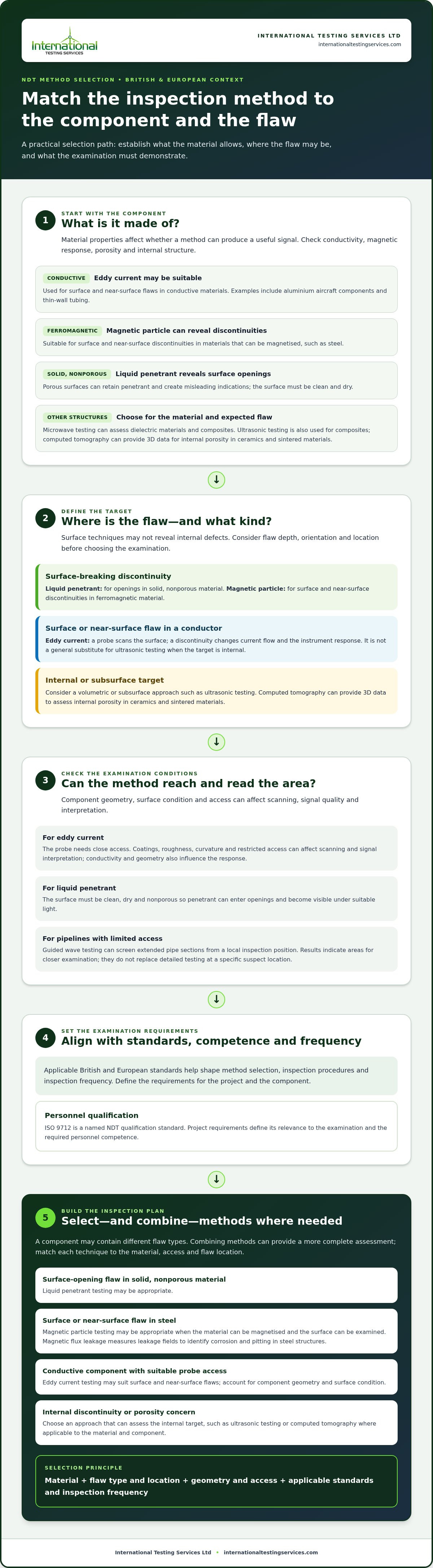
The most familiar NDT method is not automatically the right one. Knowing how to choose an NDT inspection method means matching the technique to the material, the flaw’s type and location, and the component’s geometry and access. Applicable British and European standards, along with inspection frequency, also shape the decision.
It is natural to begin with familiar methods such as ultrasonic, radiographic, magnetic particle and liquid penetrant testing. Each has different capabilities, so the choice depends on what you need to detect and where it may be. A method suited to surface-breaking flaws, for example, may not provide the evidence needed to assess an internal discontinuity.
This article explains how material properties, flaw depth and orientation, standards and risk inform method selection. It also shows how methods can complement one another, helping engineers and inspection teams choose an approach that supports a reliable assessment and documented compliance.
Key Takeaways
- Match the inspection method to the material: conductivity, porosity and ferromagnetic properties affect which techniques can produce useful results.
- Consider flaw location, orientation and geometry; methods suited to surface discontinuities may not reveal internal defects.
- Eddy current testing may be an option for conductive materials, depending on the component and available surface access.
- Use applicable British and European standards to shape method selection, inspection procedures and frequency.
- Combining methods can provide a more complete assessment when a component may contain different flaw types.
Eddy current testing
Eddy current testing uses electromagnetic induction to identify flaws in conductive materials. An alternating current in a probe creates a changing magnetic field, inducing currents in the component. A discontinuity changes the current flow and the instrument’s response. The operator scans the probe across the surface and assesses signal changes. Aluminium aircraft components and thin-wall tubing are common applications because the method can examine conductive materials without access to the opposite side.
Surface condition and access affect the examination. The probe needs close access to the inspection area, so coatings, roughness, curvature and restricted access can affect scanning and signal interpretation. Eddy current testing suits surface and near-surface flaws; it is not a general substitute for ultrasonic testing when the target is internal. Material conductivity and geometry also affect the response, so the procedure needs to account for the component.
For British and European applications, inspector qualifications should align with the governing specification and applicable procedure. ISO 9712 is a named NDT qualification standard; the project requirements define its relevance to the examination and required personnel competence.
Equipment and preparation vary by method. Eddy current testing uses an instrument and probe to scan the surface. Magnetic particle testing requires magnetising equipment and ferromagnetic particles, and the examination surface must allow particles to gather at relevant leakage fields. Liquid penetrant testing uses penetrant, remover and developer on a clean, dry, nonporous surface. Guided wave testing uses ultrasonic transducers coupled to the pipe, with access needed for installation and signal assessment. Each method requires operators who can follow the procedure and distinguish indications from noise or surface effects.
Guided wave testing sends low-frequency ultrasonic waves along structures such as pipelines. It can screen extended pipe sections from a local inspection position, which is useful where access along the full line is limited. Results indicate areas requiring closer examination; they do not replace detailed testing at a specific suspect location.
Magnetic particle testing locates surface and near-surface discontinuities in ferromagnetic materials. The component is magnetised, then particles gather where a flaw disrupts the magnetic field. The method can identify cracks in steel, provided the material can be magnetised and the surface examined.
Magnetic flux leakage also uses magnetisation, but measures leakage fields to identify corrosion and pitting in steel structures. Liquid penetrant testing reveals surface discontinuities in solid, nonporous materials when penetrant enters openings and becomes visible under suitable light. A surface-opening crack may suit penetrant testing; concealed internal damage requires a different examination. Choose the method according to the material, access and flaw location.
How does the material type affect your NDT method choice?
Material properties determine whether an inspection technique can reliably detect the target flaw. Conductivity, magnetic response, porosity and internal structure all influence a method’s suitability.
Material Compatibility and Method Suitability
Material compatibility means choosing a method whose physical principles work with the component being examined. This matters because a technique can miss relevant indications when the material blocks, distorts or weakens its signal.
For example, liquid penetrant testing reveals surface discontinuities in solid, nonporous materials. Penetrant enters openings and becomes visible under suitable light, but porous surfaces can retain it and create misleading indications. Surface condition therefore affects interpretation as well as preparation.
Microwave testing can assess dielectric materials and composites by detecting changes in their properties. Ultrasonic testing is also used for composites, while computed tomography can produce three-dimensional data to assess internal porosity in ceramics and sintered materials. These methods address different structures, so the expected flaw and component geometry guide the choice.
Inspection of Metallic Materials
Metallic materials vary in conductivity, magnetic properties and thickness, so no single method suits every alloy or discontinuity. Matching the method to the metal matters because the same flaw can produce different inspection responses in different materials.
Magnetic particle testing applies to ferromagnetic materials such as steel and reveals surface or near-surface discontinuities. Eddy current testing uses electromagnetic induction in conductive materials, while ultrasonic testing can examine subsurface features. Material identification, including positive material identification, can help establish the alloy before the examination is defined.
For manufactured components, the inspection plan should distinguish the base material, weld or casting, and the required flaw location. A surface technique may not assess internal porosity; a volumetric method may provide more relevant evidence. Destructive testing removes or damages material for examination, whereas NDT assesses components without permanent damage.
Safety precautions depend on the method and equipment. Apply the relevant risk assessment and procedure, control access for radiographic testing, and follow product handling instructions for penetrant materials. Magnetic and ultrasonic equipment also require competent operation and safe work practices suited to the inspection setting.
For ceramics, computed tomography can reveal internal porosity and structural anomalies through volumetric imaging. Porous materials require particular care with penetrant testing because absorbed penetrant can obscure meaningful indications. In manufacturing, choose the method according to whether the target is a visible surface opening or an internal feature.
Composite inspection also depends on construction and flaw orientation. Ultrasonic testing can assess composites, while microwave methods can detect changes in dielectric properties. A layered composite with suspected delamination presents a different examination problem from a ceramic part with internal voids, so material and flaw information should shape the procedure.
Material compatibility is one part of method selection; the next decision is whether the flaw is surface-breaking, near-surface or internal. A material-specific NDT inspection can align examination techniques with the component and the required assessment.
Defect type, geometry, and location
Inspection depends on the suspected discontinuity and its location. Surface methods include magnetic particle and liquid penetrant testing; ultrasonic and radiographic testing can assess internal flaws.
Surface and Subsurface Defects
Surface defects break through the component’s outer boundary, while subsurface defects lie beneath it. This distinction determines which signals can reach the flaw. Magnetic particle testing identifies surface and near-surface discontinuities in ferromagnetic materials. Liquid penetrant testing reveals discontinuities open to the surface of solid, nonporous materials.
For internal defects, ultrasonic testing sends sound through the material and evaluates reflected signals. Radiographic testing creates an image of internal structure, making density differences associated with volumetric defects visible. A surface crack in a steel weld and internal porosity in a casting therefore call for different examination capabilities.
Defect Geometry and Location
Defect geometry describes a flaw’s shape and orientation; location describes where it lies relative to the surface and inspection access. Both matter because a flaw’s position and alignment can affect whether a method detects it.
Ultrasonic testing can detect planar defects oriented perpendicular to the sound beam and provide precise depth measurements. Beam direction therefore matters when a weld may contain a planar crack. Radiographic testing is effective for volumetric defects such as porosity, inclusions and voids, which appear as contrast differences in an image.
For ultrasonic examination, compression waves help detect parallel surface cracks or fractures and material voids or porosity. Shear waves help identify laminations, delaminations and embedded inclusions. Choose the wave mode to suit the expected flaw orientation and position, not simply because the component is accessible.
Eddy current testing detects flaws in conductive materials through changes in electromagnetic response. Its use depends on probe access and material conductivity, while defect depth and orientation influence the signal. It suits surface and near-surface examination, not every internal discontinuity.
Radiographic and ultrasonic methods can provide complementary evidence when a weld or casting may contain different defect geometries. For example, radiography can reveal volumetric porosity, while ultrasonic testing can assess planar flaws and their depth. The inspection plan should specify the target flaw, its likely location and the required examination coverage.
Before choosing a technique, record the suspected defect type, orientation and position. A surface-breaking crack, a subsurface lamination and internal porosity present distinct detection problems. This description helps align the method and examination procedure with the inspection objective.
Industry standards and inspection frequency
Standards define acceptable examination methods, personnel qualifications and reporting requirements. Inspection frequency is a separate planning decision, shaped by applicable rules, component criticality and expected deterioration.
For British and European projects, ISO 9712 and EN 473 appear among the named NDT standards. Their relevance depends on the governing contract, sector requirements and applicable edition. A written examination procedure should identify the method, component scope, acceptance criteria and required records. This prevents a technically suitable technique from being applied outside the project’s compliance framework.
Other standards address particular industries or qualification systems. Recommended Practice No. SNT-TC-1A and ANSI/ASNT CP-105 are named references in the research material, while ASME, AWS and EN standards may specify accepted methods for an application. For a European fabrication contract, the governing EN requirement and purchase specification should align on the inspection technique and acceptance criteria.
Inspection intervals depend on the asset and the governing requirement, not on a single universal NDT timetable. API 570 provides guidance on the frequency of ultrasonic testing and visual inspections for piping. API 653 states that internal and external storage tank inspections must be done at least every 5 years. These named intervals apply within their specified standards and scope, rather than serving as general intervals for all components.
Risk also affects inspection frequency. Critical safety components should be inspected more frequently than standard, low-risk components. A piping circuit exposed to damaging service conditions may need a different inspection plan from a stable, lower-risk component. The programme should link prior findings, deterioration mechanisms and operating conditions to the next examination date.
Statutory inspection periods and NDT schedules are not interchangeable. In the UK, lifting equipment other than equipment used to lift people must be inspected every twelve months, according to the Health and Safety Executive. This is an equipment inspection interval, not a universal NDT requirement; the applicable duty and examination scope determine the assessment needed.
For each component, establish the governing standard, required method and inspection interval in the documented plan. Record the reason for the chosen frequency and revise it when findings or service conditions change. For example, a new indication in a critical weld may justify closer monitoring under the applicable procedure, while routine penetrant testing should follow its specified technique and acceptance criteria.
Clear records support continuity across inspection cycles. Identify the component, method, coverage, results and next due date, then retain them with the relevant procedure. These records let engineers compare findings over time and demonstrate how standards and risk informed inspection frequency.
In the United States, NDT inspectors must meet the personnel qualification requirements of the governing standard and project. SNT-TC-1A and ANSI/ASNT CP-105 are named references, but the applicable framework determines the required qualifications.
Matching NDT methods to flaw location and material
Method selection is more reliable when the inspection plan links three details: material, flaw location and flaw form. A crack at the surface of steel and porosity inside a casting require different examination coverage.
For critical components, combine methods when one technique cannot address all credible flaw types or locations. Define the target for each examination, then document how the combined results support the assessment. More methods are not automatically better; each should meet a distinct inspection need.
For ferromagnetic steel, magnetic particle testing can locate surface and near-surface discontinuities. Liquid penetrant testing reveals surface openings in solid, nonporous materials. These techniques suit surface-breaking flaws, not concealed internal porosity. Material properties therefore set the first boundary for method selection.
Assessing internal flaws calls for techniques that examine through the component. Radiography images internal structure and can reveal volumetric defects, including porosity, inclusions and voids. Ultrasonic testing can identify planar defects and provide depth measurements, particularly when the flaw is suitably oriented relative to the sound beam.
An aerospace component illustrates why the inspection objective matters. Eddy current testing is used in aircraft maintenance for conductive materials, while ultrasonic testing can assess subsurface discontinuities. The plan should distinguish the inspection zone and expected flaw type rather than treating either method as a universal examination.
Use a coverage matrix to assign methods to component zones and flaw families:
- Surface cracks: Select magnetic particle testing for ferromagnetic material, or liquid penetrant testing for a suitable nonporous surface.
- Internal porosity: Consider radiography, which can show density variations in an image.
- Planar flaws: Consider ultrasonic testing, accounting for beam direction and flaw orientation.
For a critical weld, for example, radiography may assess volumetric indications while ultrasonic testing targets planar flaws. Each procedure should define its inspection area, method, acceptance criteria and reporting requirements. Interpret results from different methods according to their specific capabilities, rather than treating them as interchangeable measurements.
Method combinations also depend on geometry and access. A curved surface, restricted probe access or complex assembly can limit practical coverage. Record these constraints in the inspection scope, then select complementary techniques that address remaining blind areas without duplicating examinations.
Align a component-specific inspection plan with its material and suspected flaw locations through NDT method planning and inspection.
International Testing Services Ltd: Phased Array Inspection
International Testing Services Ltd provides Phased Array Inspection for projects requiring focused assessment of welds or other components. When the inspection plan calls for ultrasonic examination, Phased Array Inspection and TOFD Inspection can support evaluation of internal indications, while conventional Ultrasonic Inspection and Magnetic Particle Inspection meet different examination needs.
Use these inspection services when material, flaw location, geometry and applicable acceptance criteria need to inform the examination scope. A clearly defined inspection objective helps align the method with the component and the evidence required for assessment. International Testing Services Ltd provides inspection services suited to the defined scope.
Contact International Testing Services Ltd to discuss your inspection requirements.
Set the next inspection decision in motion
A sound inspection plan should remain useful as components move through service, repair and future assessment. Record the inspection objective and the evidence needed to support the next engineering decision. This gives teams a consistent basis for reviewing findings and refining future scopes.
Understanding how to choose an NDT inspection method also means translating the objective into a defined examination. International Testing Services Ltd provides Phased Array Inspection, TOFD Inspection and Ultrasonic Inspection for projects requiring these techniques. The appropriate scope depends on the component and inspection requirements.
For a planned examination, contact International Testing Services Ltd to discuss the inspection requirements and relevant service. A clearly defined scope is a practical starting point for dependable inspection planning.
Frequently Asked Questions
What Are The Most Common NDT Methods?
Common industrial methods include visual testing, liquid penetrant, magnetic particle, eddy current, ultrasonic and radiographic testing. Their practical roles differ: a maintenance team might use visual testing to assess accessible surfaces, then select a specialist examination if the component’s condition or inspection objective calls for it. For a planned weld assessment, the governing specification and acceptance criteria help determine the appropriate method or combination.
How do you know if your chosen NDT method is reliable?
Reliability depends on method validation, qualified personnel, calibrated and maintained equipment, and a documented procedure that meets applicable standards. The procedure should define the examination scope and how indications are recorded and assessed. Probability of detection studies can estimate the likelihood of detecting a defect of a given size under defined conditions. These controls support a defensible result, but they do not make different methods interchangeable.
What Other NDT Methods Are Used for Specialized Applications?
Specialized applications may use acoustic emission to monitor energy released during crack formation or growth, or infrared testing to map thermal anomalies in electrical and mechanical systems. Vibration analysis assesses machinery imbalances and misalignment. Ground penetrating radar images subsurfaces for utility or geotechnical work. Computed tomography can produce three-dimensional data for ceramic components, while microwave testing can examine changes in dielectric materials and composites.
What factors should you consider when selecting an NDT method?
Start with the inspection objective, then consider material properties, suspected flaw, location, geometry, access, surface condition and required examination coverage. The governing specification and acceptance criteria matter too. To choose an NDT inspection method for a Scottish project, align the procedure with applicable British or European requirements and the component’s service context. A useful plan states what must be detected and what evidence the examination must provide.
What is Non-Destructive Testing (NDT)?
Non-destructive testing examines a material or component without causing permanent damage, allowing it to remain available for service or further assessment. For example, an inspector can examine a weld and document relevant indications without cutting out a sample. NDT supports inspection during manufacture, installation and maintenance. The method must still match the examination objective, since each technique has defined capabilities and limitations.
What’s the difference between X-ray and ultrasonic NDT?
X-ray testing uses radiation to create an image of a component’s internal structure; ultrasonic testing uses high-frequency sound and evaluates returning signals. Radiographic images can show volumetric features through density contrast, while ultrasound can provide depth information for suitable flaws. The outputs differ: radiography produces an image for interpretation, whereas ultrasonic results depend on probe position, sound path and signal assessment.
What are the main nondestructive testing (NDT) methods and how do they work?
The main methods use different physical signals. Visual testing examines accessible surfaces; penetrant testing makes surface openings visible; magnetic particle testing reveals magnetic leakage at discontinuities in ferromagnetic parts. Eddy current testing measures changes in induced currents in conductive materials. Ultrasonic testing interprets sound reflections, while radiography records transmitted radiation as an image. These principles explain why one technique cannot answer every inspection question.
How do you choose an NDT method based on material, thickness, geometry, and defect type?
Consider these details together rather than treating thickness or material as a standalone rule. For example, a curved component with restricted probe access may limit ultrasonic scanning, while a conductive, thin-wall part may suit eddy current examination. Then identify whether the target is a surface opening, planar discontinuity or volumetric flaw. Confirm that the selected procedure provides the required coverage and aligns with applicable acceptance criteria.


