
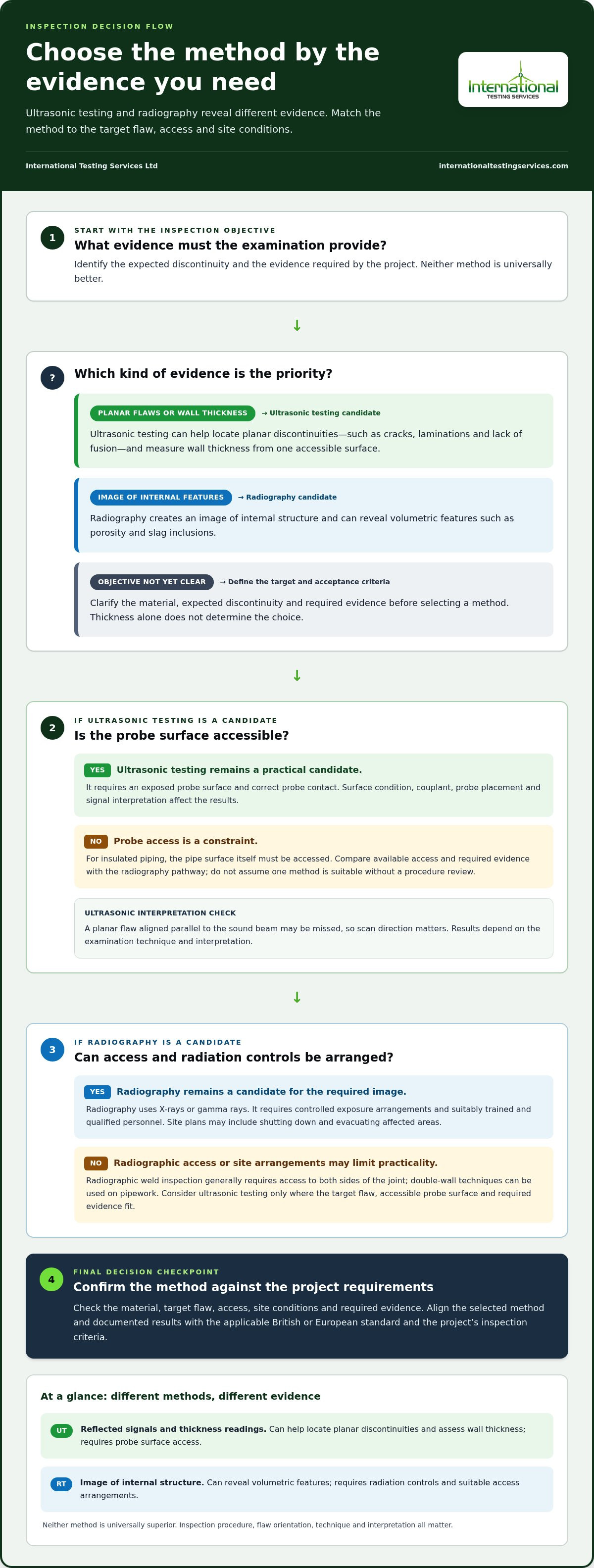
The right method depends on the flaw, material, access and inspection objective. In ultrasonic testing vs radiography, ultrasonic testing is often suited to finding planar flaws and measuring wall thickness from one accessible surface. Radiography can produce an image of internal features such as porosity and inclusions. Neither method suits every inspection.
Both methods can reveal defects that a surface examination cannot, but they provide different evidence and have different access and safety requirements. The choice should also meet the applicable British or European standard and the project’s inspection requirements.
This comparison explains how each method performs for different material thicknesses, flaw types and access conditions, and what to consider when choosing an inspection approach. It also describes how code requirements affect the decision, helping you assess which method best supports the component’s integrity and compliance objectives.
Key Takeaways
- Choose an inspection method according to the material, access, expected flaw type and inspection objective, rather than treating either method as universally superior.
- Compare the evidence each method provides: ultrasonic inspection can help locate planar discontinuities and assess wall thickness, while radiography creates an image of internal features.
- For one-sided access, ultrasonic testing may be suitable when the probe surface is accessible; radiographic weld inspection generally requires access to both sides of the joint.
- Account for radiation controls, site conditions and the project’s applicable British or European requirements when planning the inspection.
- Use the decision guide to identify when phased array inspection or another ultrasonic technique may suit the component and inspection objective.
Comparing inspection of different material thicknesses
Material thickness alone doesn’t determine the inspection method. The application, material, expected discontinuity and available access all affect whether ultrasonic testing or radiography will provide useful evidence. For example, ultrasonic testing can measure wall thickness and inspect welds. Radiography has high penetration capability but can be less effective on very thick sections or complex geometries.
Inspection speed also varies. Ultrasonic testing displays returning signals during examination, so the operator can assess the component as the probe moves. Radiography generally takes longer to set up and complete, although digital imaging can provide stored images for review.
A demonstration of probe movement and signal response shows how ultrasonic inspection works in practice:
Use the table to compare six approaches by access, output and application. These methods are not interchangeable: for example, a drone-assisted visual survey cannot provide the same internal evidence as radiography or ultrasonic testing.
| Inspection option | Thickness and access | Typical output |
|---|---|---|
| Conventional ultrasonic | Probe needs surface access | Thickness readings and reflected signals |
| Phased array ultrasonic | Probe access; can suit larger inspection areas | Directed sound-beam data |
| TOFD ultrasonic | Requires access to the inspection surface | Time-based flaw sizing information |
| Radiography | High penetration; access depends on technique | Image of internal structure |
| Robotic crawler with phased array | Can traverse large or hard-to-reach areas | Ultrasonic inspection data |
| Drone-assisted visual survey | Can reach elevated external surfaces | Visual observations, not internal flaw data |
Choose a method based on the inspection objective, not thickness alone. For a weld with suspected planar flaws, ultrasonic methods can help locate and size relevant reflectors. Radiography can provide an image of internal volumetric features. Material attenuation matters too: highly attenuating materials can limit radiographic examination.
Access affects which method is practical. Conventional ultrasonic testing requires an exposed probe surface, so insulated piping must be accessed at the pipe itself. Radiographic weld inspection generally requires access to both sides of the joint, although double-wall techniques can be used on pipework. A remote crawler can carry phased-array probe heads across selected areas, while a drone can support visual checks where direct access is difficult.
Operator skill affects both examination and interpretation. Ultrasonic results depend on probe placement, surface condition, couplant and the operator’s interpretation of signals. Radiographic work requires controlled exposure arrangements and image interpretation. Neither method is destructive, but each has limitations that the inspection procedure must address. For British and European projects, align the selected method and documented results with the applicable project requirements.
Match the method to the material, target flaw, access conditions and required evidence, then confirm that the procedure meets the project’s inspection criteria.
Radiography Testing vs Ultrasonic Testing: Which One is Better?
Neither method is universally better for weld inspection. The right choice depends on the defects being assessed, the evidence required, site conditions and the applicable British or European requirements.
Radiography Safety and Site Disruption
Radiography uses X-rays or gamma rays, so ionising radiation must be managed as part of the inspection plan. Suitably trained and qualified personnel should perform radiographic inspection because exposure can present serious health and safety risks. Site arrangements may include shutting down and evacuating affected areas before testing.
Radiography can disrupt nearby work more than ultrasonic testing, which has no radiation-related requirements and can suit inspection in an active industrial facility. Both methods still require safety and environmental considerations. Radiography’s access and exposure arrangements can limit where and when it is practical, while ultrasonic testing requires accessible surfaces and correct probe contact.
Inspection Accuracy and Reliability
For weld inspection, accuracy depends on the discontinuity, examination technique and interpretation of results. Radiography can reveal volumetric defects, including porosity and slag inclusions, in an image of the weld’s internal structure. Ultrasonic testing is effective for locating planar discontinuities such as cracks, laminations and lack of fusion, and can help establish their position.
Ultrasonic results depend on probe placement, surface condition and coupling material. A planar flaw aligned parallel to the sound beam may be missed, so scan direction matters. Radiography can also miss flaws that do not produce sufficient image contrast. Neither method is reliable simply by name: the inspection procedure must suit the weld and its acceptance criteria.
Testing Costs
The price depends on the case and is given after a quote request; cost factors include the inspection method, component geometry, access, preparation and examination scope. Radiography may require additional site arrangements for radiation control, including area evacuation where necessary. Ultrasonic testing avoids radiation-related controls, but still requires appropriate equipment, surface access and qualified operators.
There is no meaningful universal cost ranking between the methods. Inspecting a small weld with accessible probe surfaces differs from achieving radiographic coverage on complex geometry. Compare the complete inspection scope and site requirements, rather than equipment frequency or a single headline rate.
Equipment and Preparation
Ultrasonic testing typically uses an instrument and probe to send and receive sound waves. A couplant helps transmit vibrations into the component. Preparation includes exposing the probe surface and addressing its condition so the operator can obtain and interpret signals. The operator may adjust probe position and scan direction to examine the weld.
Radiography uses an X-ray or gamma-ray source and a recording medium or digital imaging system to create an image. The source and detector arrangement must suit the component and technique. Preparation also accounts for radiation controls and possible evacuation. Unlike ultrasonic testing, radiography produces image evidence, while ultrasonic inspection provides information through reflected signals.
For a practical decision, match the method to the expected defect type, weld geometry, access, safety controls and project criteria. Where radiation-related disruption is difficult to accommodate, ultrasonic testing may be more suitable. Where an image of internal structure is required, radiography may be appropriate.
How ultrasonic testing detects internal flaws
Ultrasonic testing sends high-frequency sound waves into a component and detects energy reflected by internal discontinuities. A probe introduces the waves through a couplant, often a thin oil film, which transfers vibration into the material. This non-destructive examination assesses material integrity without cutting or breaking the component, unlike destructive testing.
In conventional testing, the operator places a hand-held probe on the prepared surface. The probe sends and receives sound waves at the same location. As the waves travel through the material, boundaries and flaws reflect energy back. The instrument displays the returning signals, which the operator interprets to determine a reflector’s position and assess its relative response.
Ultrasonic testing is effective for planar flaws, including cracks, laminations and lack of fusion in welds. These discontinuities can reflect sound strongly when the beam meets them at a suitable angle. Signal arrival time helps locate a flaw, while relative amplitude provides information about the reflector. In a weld examination, this can help identify an indication’s depth and position.
Beam orientation matters. An ultrasonic beam may miss a planar defect aligned parallel to its path because little sound returns to the probe. Operators choose probe positions and scan directions to examine the weld from suitable angles. Surface condition and couplant also affect signal quality. Rough or inaccessible surfaces can hinder probe contact, so the procedure must account for them.
Phased array ultrasonic testing uses multiple transducers to direct sound through the material. Steering beams at different angles can examine weld regions from varied directions. Time of Flight Diffraction, or TOFD, uses a transmitter and receiver; sound travel time helps create an image of material integrity. These techniques provide ultrasonic data, not a radiographic image.
Radiography uses X-rays or gamma rays to form an image of internal features. It is effective for volumetric defects such as porosity and slag inclusions, and can reveal cracks and voids in welds. Radiographic images show density differences across the material. The ultrasonic testing vs radiography comparison therefore depends partly on whether the inspection requires reflected-signal information or image evidence.
The methods reveal different evidence. Ultrasonic testing can help locate planar discontinuities, while radiography displays internal density variations. For example, suspected lack of fusion may call for careful ultrasonic beam orientation, while porosity may be visible through radiographic contrast. This practical distinction matters in an ultrasonic testing vs radiography assessment, but neither method detects every flaw in every orientation or material.
Ultrasonic testing on thick sections and one-sided access
Ultrasonic testing can examine a component from one accessible surface, while radiographic weld inspection generally requires access to both sides. Section thickness, geometry and the required flaw information influence the technique and probe arrangement.
Thick-Section Inspection
For a thick section, the transducer sends sound waves into the material and receives reflections from its internal structure. The timing and strength of returning signals help the operator assess reflector position and material thickness. This provides information from inside the component, unlike a surface-only visual examination.
Thickness alone doesn’t establish whether ultrasonic testing is suitable. Material properties, geometry and the target flaw affect how sound travels and returns. Radiography has high penetration capability, but highly attenuating materials, very thick sections or complex geometries can limit its effectiveness. Let the inspection objective guide technique selection.
For example, a thick weld with a suspected planar flaw requires an ultrasonic scan that directs sound toward the relevant region. A radiographic image may provide different evidence, particularly for volumetric features. Neither approach removes the need to consider material and access conditions when setting the examination procedure.
One-Sided Access
Ultrasonic testing can examine a component from one side, provided the probe surface is accessible. The operator moves the transducer across that surface, allowing sound waves to enter the material and return from internal reflectors. This can suit components where the opposite face cannot be reached.
Radiographic weld inspection generally requires access to both sides of the joint, although double-wall techniques can be used on pipework. Ultrasonic testing does not require a source and recording medium on opposing sides, but it still needs direct probe contact. For insulated piping, conventional ultrasonic testing requires access to the pipe surface.
Access means more than reaching the component’s general location. The probe needs contact with the examination surface, and its position must allow the required scan. In a confined installation, a one-sided setup may be practical only if the selected surface is exposed and reachable.
Flaw Sizing and Wall-Thickness Measurement
Ultrasonic measurements can assess wall thickness and corrosion loss from an accessible surface. The instrument uses sound travel time to calculate the distance through the material. Recording readings by location creates a traceable picture of thickness variation across a pipe or vessel.
For flaw assessment, signal timing helps locate a discontinuity, while reflected signal characteristics help evaluate its size and depth. The result depends on scan direction and the flaw’s orientation relative to the sound beam. A planar defect aligned parallel to the beam may produce a weak response.
When previous inspection data is available, comparable ultrasonic readings can help assess changes in equipment condition over time. For example, wall-thickness measurements taken at defined pipe locations can be compared during later inspections. Consistent locations and documentation make the comparison more useful for monitoring component integrity.
Choose the technique by matching access, material, geometry and required information, then define the scan and measurement locations in the inspection procedure.
Code and compliance considerations
Code compliance depends on the requirements governing the component, weld and project. The selected method must meet those requirements and produce records that support the required acceptance decision. For British and European work, identify the applicable project standards and specification before choosing ultrasonic testing or radiography. A method’s technical capability alone doesn’t establish compliance.
Start with the governing requirements
Review the contract, inspection plan and applicable British or European standards to establish the required examination method, coverage, procedure and acceptance criteria. These requirements determine whether ultrasonic testing, radiography or both are appropriate. Radiography may be preferred when the project code specifically requires it. A technically suitable alternative cannot automatically replace a prescribed method.
AWS, ASME and API requirements also apply to weld inspections when a project specifies those frameworks. AWS and ASME increasingly accept ultrasonic testing for condition monitoring and life-extension programmes, while AWS, ASME and API have long-standing acceptance of radiographic testing for manufacturing and fabrication compliance. Treat each named code as relevant only when the project requirements identify it.
Personnel, procedures and records
Operators of both methods require specialised training and certification. Their work involves following an examination procedure, applying the specified scan or exposure arrangement, and evaluating indications against the applicable acceptance criteria. Qualification supports consistent inspection, but the written procedure must also address the component, material, weld geometry and required coverage.
For ultrasonic testing, records should identify the inspection area, technique, equipment settings and relevant indications. The procedure should account for probe direction because a flaw’s orientation can affect the returned signal. Radiographic records include images produced using X-rays or gamma rays, with the examination arrangement and interpretation documented for review.
Demonstrating compliance
Before inspection, align the method with the project specification and document the examination scope. During the work, maintain traceability between the component, inspection location, operator and result. Afterward, compare recorded indications with the acceptance criteria instead of relying on a general statement that the weld passed. This sequence makes the decision auditable.
Where requirements permit a choice, compare the evidence each method provides. Ultrasonic signals can locate and size certain planar flaws; radiographic images can show volumetric discontinuities and internal geometry. Some projects combine both methods when one examination does not provide the required evidence. The governing specification, not a general preference, should define that combination.
For support interpreting radiographic examination requirements, use radiography interpretation services to assess whether the inspection evidence aligns with the project’s specified criteria.
International Testing Services: Phased Array Inspection
International Testing Services Ltd provides Phased Array Inspection for projects requiring focused ultrasonic examination of welds and components. Phased array directs sound beams through material at different angles, supporting assessment of internal discontinuities where scan coverage and flaw orientation matter.
For weld integrity decisions, choose the technique according to the inspection objective, component geometry and applicable British or European requirements. TOFD Inspection and Ultrasonic Inspection are also relevant when a project calls for those ultrasonic examination methods. These services help align the examination approach with the evidence required for the component and its acceptance criteria.
To discuss an inspection requirement, contact International Testing Services Ltd through internationaltestingservices.com.
Set the Inspection Plan Before Work Begins
Turn the decision on ultrasonic testing vs radiography into a defined inspection plan before work begins. Record the component, inspection objective, applicable British or European requirements, and evidence needed for acceptance. This gives the project team a clear basis for aligning examination procedures, reporting and review.
For scopes involving complex welds or critical industrial components, technical oversight can help maintain consistency between the chosen method and project criteria. International Testing Services provides phased array, TOFD and ultrasonic inspection to support assessment against the inspection objectives established for the work.
Set out the examination requirements and discuss the appropriate inspection approach with International Testing Services. A clear, documented plan is a practical next step towards dependable inspection decisions.
Frequently Asked Questions
What’s the difference between UT and radiography in NDT?
Ultrasonic testing interprets sound-wave reflections, while radiography produces an image using X-rays or gamma rays. This distinction affects the evidence available for a decision: ultrasonic results can indicate reflector position and depth, while radiographic images show internal density variations. For a weld record, establish whether the project needs signal-based flaw information, an image for review, or both. The specified inspection criteria should determine the required evidence.
How does ultrasonic testing work compared with radiographic testing?
Ultrasonic testing uses a probe and couplant to transmit sound into a component, and the operator interprets returning signals during scanning. Radiography positions a radiation source and recording medium to produce an image for interpretation. Digital radiography can store images electronically. For example, a reviewer can assess a saved radiographic image, while ultrasonic assessment relies on recorded signals and examination data linked to the inspected location.
What defects can ultrasonic testing detect versus radiography?
Ultrasonic testing can locate planar discontinuities such as cracks, laminations and lack of fusion, while radiography is effective for volumetric flaws such as porosity and slag inclusions. A weld with suspected lack of fusion may call for examination from suitable ultrasonic beam directions. Suspected porosity may be assessed through radiographic contrast. The inspection objective determines whether one method provides suitable evidence or whether the project requires complementary examination.
What are the advantages and disadvantages of ultrasonic testing and radiography?
Ultrasonic testing can examine from one accessible side and provide information about flaw location and wall thickness, but probe contact and flaw orientation affect the response. Radiography provides an image of internal structure but involves ionising radiation and may require site evacuation. Compare access, expected defect type, required records and site constraints. Each method’s practical value depends on whether it meets the project’s inspection and acceptance requirements.
What materials and thicknesses are suitable for ultrasonic testing versus radiography?
Both methods can examine ferrous and non-ferrous materials, but material properties influence their suitability. Ultrasonic testing can inspect welds and smaller components when the probe surface is accessible. Radiography has high penetration capability, though highly attenuating materials can limit examination. No single thickness threshold applies to every application. Assess material, geometry, access and target flaw together before specifying the method.
How long does ultrasonic testing or radiographic testing take?
Radiographic testing generally takes longer to set up and complete than ultrasonic testing, but the total duration depends on the component and examination scope. Access, surface preparation, coverage and interpretation affect the schedule. Digital radiography can provide faster image turnaround than film-based processes. For a weld inspection plan, account for site arrangements and reporting as well as examination time.
What safety risks and radiation precautions apply to radiographic testing?
Radiographic testing uses ionising radiation, which can create serious health risks if not properly managed. Suitably trained and qualified personnel must perform the examination, and on-site work may require affected areas to be shut down and evacuated. The inspection plan must account for site conditions and radiation controls before exposure begins. Ultrasonic testing has no radiation-related hazards, though it still requires suitable safety and environmental controls.
What codes and standards govern ultrasonic and radiographic testing in the United States?
For projects in Britain and Europe, identify the governing standards and examination requirements in the contract, specification and inspection plan. Apply the requirements relevant to the project rather than assuming a standard from another jurisdiction governs the work. AWS, ASME and API frameworks are relevant when US project documents specify them. The governing documents determine the permitted method, examination scope and acceptance criteria.


