

A single thickness reading is not a corrosion map. Phased array ultrasonic testing (PAUT) uses multiple elements to steer and focus ultrasonic beams, while encoded scanning ties thickness readings to scanner position to create an area-based image. Corrosion mapping with PAUT inspection typically achieves a resolution of 1-5 mm for internal mapping.
Conventional ultrasonic testing is useful for local thickness readings, but it may not show how wall loss varies across a wider area. For in-service assets, that distinction matters: a position-linked map helps engineers locate and assess corrosion features instead of relying on isolated measurements.
This article explains how encoded PAUT mapping works, what its scan images show, and how it compares with conventional UT and radiography. It also covers where the method can support in-service inspection of Scottish pipes, tanks, vessels and other industrial assets, and the factors that shape a corrosion map’s coverage and detail.
Key Takeaways
- Understand how PAUT steers ultrasonic beams and how encoded scanning links thickness readings to precise locations.
- See how grid boundaries and spacing influence map detail, scan coverage and the visibility of small corrosion features.
- Compare area-based thickness imaging with conventional UT readings and radiographic testing to understand where each method fits.
- Learn how corrosion maps can support in-service assessment of pipes, tanks, vessels and other industrial assets.
- Recognise how Phased Array Inspection can contribute when a position-linked view of wall loss is required.
PAUT compared with conventional UT and radiographic testing
PAUT and conventional ultrasonic testing both use sound waves to assess material. Radiographic testing uses X-rays or gamma rays, producing a different inspection method and type of data.
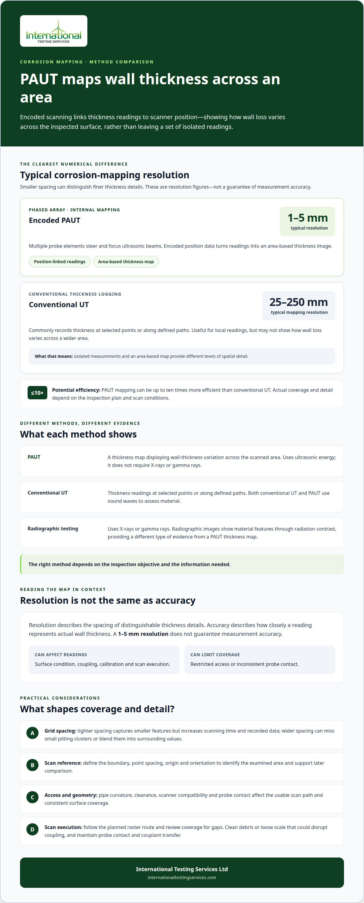
PAUT uses multiple probe elements to steer and focus an ultrasonic beam electronically. Encoded scans connect readings with position, producing area-based images rather than isolated thickness values. Typical phased-array internal corrosion mapping resolution is 1-5 mm. Larger probe footprints can cover more surface at higher speeds, while the resulting scan records thickness variation across the inspected area.
Conventional UT commonly records thickness at selected points or along defined paths. Typical corrosion-mapping resolution for conventional thickness logging is 25-250 mm, compared with 1-5 mm for phased-array internal mapping. PAUT mapping can be up to ten times more efficient than conventional UT, though actual coverage and detail depend on the inspection plan and scan conditions.
Radiography uses ionising radiation, whereas PAUT uses ultrasonic energy and does not require X-rays or gamma rays. The methods provide different evidence: radiographic images show material features through radiation contrast, while a PAUT thickness map displays wall-thickness variation across a scanned area. The right method depends on the inspection objective and the information needed.
Equipment size and power consumption are practical considerations. PAUT electronics control beam steering, while an encoder tracks scanner movement; a complete setup may also include a probe, scanner and display. The equipment footprint and power demand depend on the components and site arrangements, so consider them alongside access and coverage requirements.
Pipe Diameter and Scanner Compatibility
Pipe diameter and scanner compatibility determine whether equipment can maintain suitable contact and movement on a pipe’s curved surface. Stable probe positioning supports consistent coverage across the inspection area. Pipe geometry, available clearance and the scanner’s contact arrangement affect the usable scan path. A scanner suited to a broad surface may not fit a tight curvature or restricted access route.
Accuracy, Resolution, and Limitations
Resolution describes the spacing of distinguishable thickness details, while accuracy describes how closely a reading represents actual wall thickness. PAUT corrosion mapping typically offers 1-5 mm resolution for internal mapping, but that figure is not a measurement-accuracy guarantee. Surface condition, coupling, calibration and scan execution affect readings. Restricted access or inconsistent probe contact can also limit coverage and the interpretation of local corrosion features.
Repeatability and Inspection Conditions
Repeatability means reproducing comparable measurements and scan coverage during a later inspection. It matters when engineers compare wall loss over time. A defined scan boundary, orientation and position reference support meaningful comparisons. Before scanning, remove debris or loose scale that could disrupt coupling, then maintain probe contact and couplant transfer across the area. Access must let the scanner follow its planned path without leaving gaps.
Grid-based scanning and scan boundaries
A corrosion map is useful only when its readings correspond to a defined area and position. The grid provides that reference, while scanner design and access determine how consistently the surface can be covered.
Before scanning, establish four details: the scan boundary, point spacing, origin and scan orientation. Together, they identify the examined area and give later scans a reference for comparison. For example, map a pipe section from a marked origin, recording the scan direction around its circumference and along its length.
Grid spacing determines the map’s level of detail. Tighter spacing captures smaller features but increases scanning time and the amount of recorded data. Wider spacing can miss small pitting clusters or blend them into surrounding thickness values. Set the spacing according to the inspection objective and the corrosion features to be evaluated, not convenience alone.
Raster scanning follows a back-and-forth route across a defined width and length, helping cover the selected area systematically. The operator or scanning system must stay within the boundary and avoid unscanned strips between passes. A consistent origin and orientation also make it easier to interpret the map in relation to the component.
Manual and Automated Scanning
In manual scanning, an inspector moves the probe across the grid. Semi-automated systems assist with movement, while automated scanners control travel along a planned path. The approach affects repeatability and coverage validation. Automation is not essential, but can improve speed and repeatability; manual movement may suit areas where geometry or access prevents a fixed scanner path.
The scanner must suit both the component’s curvature and the available surface. Magnetic wear shoes can help hold a scanner against suitable ferromagnetic surfaces as it travels. Fit is important: poor contact or an unsuitable route can disrupt movement and leave gaps. Select the scanner with the surface shape, raster pattern and access restrictions around the scan boundary in mind.
Corrosion Mapping Procedures
A mapping procedure defines how the grid is marked, scanned and reviewed, helping capture the full area consistently. First, define the boundary and origin, then set point spacing and orientation. Scan each raster pass across the specified width and length, following the planned route. Finally, review coverage for gaps and confirm that the map represents the intended area.
Access for a remote scanner requires planning when the inspection area is difficult to reach directly. The scan boundary and route must be workable from the available position; an obstructed path can compromise coverage. Clearly map the accessible area and record any boundary the scanner cannot reach, so results are interpreted within the actual inspection limits.
Encoded phased array corrosion mapping
Encoded phased array mapping links ultrasonic thickness readings to scanner position. An encoder tracks movement and assigns each measurement a corresponding coordinate, rather than leaving it as an unlocated reading. Corrosion mapping with PAUT inspection therefore creates a spatial record of wall condition across a defined area.
The probe’s multiple elements electronically steer and focus the ultrasonic beam. As the scanner moves, the system records thickness readings against its position. Internal phased-array corrosion mapping typically provides 1-5 mm resolution. A B-Chart can record minimum thicknesses at up to 50 samples per centimetre, creating a detailed line profile along the scan path.
A C-scan presents thickness values across the inspected area in a plan view. Its colour scale represents thickness ranges, while coordinates or grid references show where readings were taken. A B-scan, by comparison, displays a line-based profile. For example, a C-scan can show wall-loss distribution across a plate zone, while a B-scan follows a single scan line.
A useful map identifies the minimum thickness and its grid position or coordinates. This pairing lets an engineer locate the lowest reading on the component instead of relying on a colour image alone. Clear orientation and reference points relate the displayed area to the physical asset and support integrity assessment.
For Scottish projects, the governing British or European standard and project specification should set the inspection requirements. Applicable documents depend on the component, inspection purpose and contract scope; no single code governs every corrosion-mapping application.
Technicians should be qualified for the applicable ultrasonic method and inspection scope, with competence assessed against the project’s governing written practice and procedure. Inspection records should identify the technique and acquisition settings used, so reviewers can understand how the map was produced.
PAUT uses ultrasonic energy, not X-rays or gamma rays, but site hazards still need to be controlled. Before scanning, assess access and relevant working-at-height or confined-space conditions, and manage cables, couplant and equipment around the work area. Safe positioning matters because restricted access can affect operator movement and scan coverage.
Corrosion mapping with PAUT inspection supports comparison only when later scans align with the original map. Retain the coordinate reference, scan orientation, acquisition settings and minimum-thickness location. Matching these references in a subsequent inspection helps distinguish actual thickness change from differences in scan position or coverage.
PAUT applications for in-service corrosion inspection
In-service ultrasonic inspection can assess corrosion in pipes, tanks, vessels and other critical assets. Plan the application around the asset’s geometry, operating context and specific degradation concern.
Detectable Patterns and Blind Spots
PAUT can help identify pitting clusters, erosion bands, under-deposit corrosion, edge thinning and localised changes near welds or flow disturbances. These patterns can point to different areas of concern: erosion bands may follow flow paths, while edge thinning can affect component boundaries.
Corrosion under insulation is another potential inspection target. The method can assess material beneath insulation when the inspection arrangement provides suitable access and acoustic contact. Complex geometry may also be examined without extensive surface preparation, although component shape and access still affect the usable inspection area.
Blind spots occur when corrosion lies outside the examined zone or when surface condition, poor coupling or inconsistent contact interrupts data capture. Insulation, supports, attachments and restricted access can limit the areas an inspection can reach. For a vessel with congested external pipework, these restrictions should inform the interpretation of results and the scope of any follow-up examination.
Results, Wall Thickness, and Fitness for Service
Results should help asset engineers connect observed wall loss to an inspection decision. For example, a localised indication on a process pipe may warrant different follow-up from a broader erosion pattern associated with flow conditions. The report should identify the areas examined and provide enough location context for engineering review.
Remaining wall thickness is one input to fitness-for-service assessment, not a decision on its own. Engineers interpret measurements against the component’s design information, operating conditions, degradation mechanism and applicable acceptance criteria. The assessment establishes what the measured condition means for continued operation, monitoring or maintenance planning.
For piping integrity programmes, repeated examinations of defined zones can help teams evaluate changes over time. This is especially relevant where corrosion mechanisms vary along a line, such as near flow disturbances, deposits or weld transitions. Inspection findings can inform risk-based prioritisation across the system instead of treating every section alike.
For tanks and vessels, the inspection may focus on localised wall loss in a selected region or a broader condition assessment. Engineers can use the findings to identify where further evaluation is warranted and whether to consider repair, replacement or monitoring. That judgement belongs within the asset’s engineering assessment and governing acceptance criteria.
What are the step-by-step procedures for PAUT corrosion mapping?
A controlled inspection procedure connects the asset question to usable scan data. The sequence below takes the work from defining the examination objective through to reviewing the captured results.
- Clarify the inspection objective. Identify the component and the corrosion concern that prompted examination. A pipe affected by suspected flow-related erosion may need attention directed towards the relevant run, while a tank assessment may focus on a selected wall area. This objective informs the inspection scope and the information the final record must convey.
- Assess the component and access. Review the surface condition, geometry and obstacles along the proposed inspection area. Supports, attachments or insulation can restrict probe movement or limit access. Identify these constraints before scanning, so they can be considered when planning the examination and interpreting which areas the captured data represents.
- Prepare the inspection surface. Remove debris or loose scale that could disrupt coupling between the probe and material. Water is commonly used as couplant in corrosion-mapping systems. Apply and maintain suitable coupling during examination, since poor contact can interrupt ultrasonic transmission and lead to data dropouts.
- Set up the scanning equipment. Position the phased-array probe and scanner for the component geometry, then connect the encoder so movement can be associated with readings. Confirm that the arrangement can travel across the intended surface without losing contact. For a pipe, check that curvature and nearby obstructions do not interrupt the planned scan movement.
- Acquire and monitor the scan. Move the scanner across the examination area while the system records ultrasonic thickness readings and position. Observe the scan during acquisition for signs of interrupted coupling or missing data. If a dropout appears, examine whether contact, surface condition or scanner movement caused it before treating the captured area as complete.
- Review and report the results. Check the acquired data for gaps and confirm that the intended area has been represented. Record the minimum thickness with its location, and describe any limitations affecting coverage. For a pipe section, this allows reviewers to relate the reported finding to the examined component rather than treating it as an isolated reading.
The completed record should preserve the link between the inspection objective, examined area and recorded findings. This context helps an engineer interpret the results alongside the asset’s condition and determine the next assessment or maintenance decision.
International Testing Services: Phased Array Inspection
International Testing Services Ltd provides Phased Array Inspection for projects requiring ultrasonic examination of components and corrosion mapping. When an asset needs position-linked thickness data, this method can support inspection planning and documented assessment. TOFD Inspection and Ultrasonic Inspection are also available for relevant examination requirements.
Consider Phased Array Inspection when engineers need to assess wall-thickness variation across a defined area or review corrosion indications alongside other inspection findings. The right method depends on the component, inspection scope and information required. International Testing Services Ltd can discuss the inspection requirement and relevant NDT approach.
For inspection enquiries, contact International Testing Services Ltd or visit the International Testing Services website.
Set the Next Inspection Decision in Motion
A corrosion map is most useful when its findings inform a clear asset-management decision. Before the next inspection cycle, define how engineers will use the results: to prioritise areas for closer assessment, plan maintenance or establish a reference for future condition reviews. This helps inspection information support practical decisions instead of remaining an isolated report.
For Scottish asset teams, the next step is to align the inspection scope with the component, access conditions and engineering question. A focused discussion about corrosion mapping and PAUT inspection can help define the information the assessment needs to deliver and how it will support integrity planning.
International Testing Services offers Phased Array Inspection, TOFD Inspection and Ultrasonic Inspection for industrial inspection requirements. Contact International Testing Services to discuss your inspection requirements and progress your asset assessment with a defined technical objective.
Frequently Asked Questions
What Is PAUT?
PAUT, or phased array ultrasonic testing, uses multiple probe elements to steer and focus sound beams electronically. Inspectors can examine material using selected beam angles and review recorded signal data. For Scottish asset inspections, this approach can provide a more detailed view of thickness variation than a single spot reading. The required scan configuration depends on the component and inspection objective.
What is corrosion mapping in ultrasonic testing?
Corrosion mapping in ultrasonic testing records wall-thickness measurements across a defined area of a component. The resulting map helps engineers locate reduced-thickness regions and prioritise areas for assessment. For example, a mapped tank section can show whether wall loss is concentrated in one zone or spread across the scanned surface. The map represents only the area examined, so its boundaries matter when interpreting results.
What is corrosion mapping using PAUT?
Corrosion mapping using PAUT combines phased-array ultrasonic measurements with position data to create a spatial record of wall thickness. This lets engineers relate low readings to specific areas on a component. For a Scottish process pipe, that location information can help distinguish a localised indication from broader thinning and guide where further engineering assessment should focus.
How does PAUT corrosion mapping work, and what equipment is required?
A PAUT system sends ultrasonic beams into the component and records thickness readings as the probe moves. A practical setup includes the instrument, phased-array probe, scanner and encoder, couplant, and a display or data-recording system. The encoder links readings to scanner position. Surface condition and probe contact affect data capture, so the setup must suit the component geometry and planned scan area.
How does PAUT corrosion mapping compare with conventional ultrasonic thickness testing and radiography?
Conventional ultrasonic thickness testing commonly gathers readings at selected points, while PAUT mapping records thickness variation across a scanned area. Radiography uses X-rays or gamma rays rather than ultrasonic sound waves, so it provides different inspection evidence. The appropriate method depends on the examination objective, component access and information required. For example, locating and comparing wall loss across a zone calls for area-based thickness mapping.
Which industry standards and codes govern PAUT corrosion mapping in the United States?
The material identifies ASME Section V, API 1104, and AWS D1.1 as codes that recognize PAUT, but does not establish that they govern PAUT corrosion mapping in the United States.


